The original plan for this system was to make use of the onboard flash on the Nexys2 board, whose 128MB capacity seemed to offer room to place seven virtual disk cartridges and access them from the disk emulation hardware as needed. The speed of the 1130 disk is slow, with 28 microseconds between each word as the data is streaming in or out of the heads, which would appear at first glance to easily allow for use of flash to read or write the word as needed. The flash has an effective write time of 13.6 microseconds per word, but that is at best case which would require building and writing 32B buffers not individual words, with some kind of FIFO buffer between disk emulation and the flash access module.
A complication comes from the implementation on the Nexys2 board, where the address, data and most control lines are shared between RAM and flash. Only one is accessed at any given time, with RAM the clear priority to ensure the 1130 operates correctly and meets its realistic timing objective. Thus, access to flash would have to fit 'in between' the 1130 CPU and cycle steal accesses. The initial concept was to only allow flash access at phase A of a T7/X7 cycle, finishing up any flash access use of the signal lines before the 1130 itself begins RAM access.
The complexity of overlapping all this, with operations such as a write of a 32byte block taking well over 200 microseconds to complete, then needing to asynchronously empty a FIFO on that long timescale. Plus, the challenges of error recovery are thorny since the disk emulation module and 1130 program itself will have moved well past the IO by the time the last part of a sector is written. Any problem is detected long after we could have presented some meaningful status to the software running in the 1130.
At this point, I suspect that any flash or disk drive used to emulate the disk drive will be hung off a fast serial link of some sort, eliminating the shared signals that ultimately forced me to drop use of the onboard flash. More later as I redesign and implement a replacement mechanism.
\
It is also possible that I will figure out a method that safely exploits the onboard flash, which would have been the most natural approach, most efficient in space and energy use. .
Building the console hardware prototypes
Here is the wiring for half of the console lights panel for the 1130 replica - these are the lights that display the contents of IAR, SAR, SBR, ACC, EXT and AFR registers, bits 0 to 15.
Prototype boards implementing a chain of three MAX7219 chips that will drive 192 LEDs based on data sent over a three wire serial protocol link from the recreated 1130 FPGA board. This board operates at 5V and has a level shifting 74HCT00 chip to permit it to operate with signals from the FPGA which are based on 3.3V logic levels.
The board shown above will take 32 button or switch contacts and multiplex them over a two wire I2C serial bus to the FPGA 1130 machine. The board operates at 3.3V to interface with the FPGA board, but has level shifting chips to allow 5V logic levels for inputs. It is used with the debouncer board below. The buttons, toggle switches and rotary switches of the 1130 console, except for the 16 toggle switches that are mounted on the console printer faceplate, are routed through this concentrator and into the hardware on the FPGA board. Uses an MCP23017 to multiplex signals and several 74HC4050 level shifter buffers which tolerate 5V inputs and produce legal 3.3V outputs.
This debouncer will remove any bouncing of the state of the buttons as they are operated, where contacts produce a short term blizzard of on and off conditions as the physical switch is pressed or released, but the intent is to record just the selected final condition - 1 or 0 - which the switch will settle down to deliver steadily a few milliseconds after it is operated. The debouncer eliminates those glitchy short term effects and passes through only the intended change, on to off or off to on. This board as built implements debouncers for 24 switches/buttons, more chips are added as more buttons are required. Uses MC14490 debouncer chips which operate on 5V, producing the signals that are shifted down to 3.3V signals by the buffers on the concentrator board above.
The 16 toggle switches, called the Console Entry Switches, are separately multiplexed by an MCP23S17 chip which is very similar to the MCP23017 but uses the SPI protocol, a four wire serial link, rather than the I2C protocol of the other chip. Debouncing is currently done in the FPGA hardware but will be handled by MC14490 chips in the next version of the board (not pictured here).
Together, these boards allow 240 input and output devices (LEDs, buttons, and switches) to be connected using only 9 wires into the FPGA.
 |
| Wiring of 96 LEDs for the left side of console light display |
These are placed in 1:1 scale to an IBM 1130 display - the board you see is 4" by 10", the left side of the 1130 panel lights encompass a 5" by 10" space, adding in the right side produces the 20" x 5" black display that lights to indicate the contents or status of key parts of the machine. This board will sit inside the display panel box, with 1/2" clearance to the top and bottom, fronted by a smoked plexiglas plate that will recreate the lettering and cutout numerals that are lit by the LEDs in each position.
 |
| Left side of light panel - contents of six registers |
The six registers, from top to bottom, are the Instruction Address, Storage Address, Storage Buffer, Arithmetic Factor, Accumulator, and Accumulator Extension Registers, each 16 bits wide.
 |
| IBM 1130 at National Museum of Computing, Milton Keynes, England, UK |
Our light panel represents the left half of the black rectangle you can see to the right of the red 'emergency pull" switch.
 |
| LED driver boards |
 |
| Switch/Button input multiplexor board |
 |
| Input debouncer board |
The 16 toggle switches, called the Console Entry Switches, are separately multiplexed by an MCP23S17 chip which is very similar to the MCP23017 but uses the SPI protocol, a four wire serial link, rather than the I2C protocol of the other chip. Debouncing is currently done in the FPGA hardware but will be handled by MC14490 chips in the next version of the board (not pictured here).
Together, these boards allow 240 input and output devices (LEDs, buttons, and switches) to be connected using only 9 wires into the FPGA.
Interfacing the console printer mechanism
The Selectric typewriter is a purely mechanical device, using an electric motor solely as a power source to spin rods and move levers. it could as easily be powered by a steam engine or foot pedals. Thus, when IBM adapted it as a console printer (the 1053 used with the 1130 and 360 computers, the 2741 terminal used for timesharing and the I/O Selectric used to interface to minicomputers), it required a complicated set of additional mechanical components and some very careful timing and interlocking.
The keys on an ordinary Selectric move down, causing a lever to selectively pull on several rods inside the machine that select the typeball position. These are the tilt and rotate levers, where the lever for an individual key has a hook corresponding to the tilt and rotate rods it should activate, no hook for the others.Thus, movement of a key downward activates these rods. The rods are connected to a clever mechanism that converts a rotate code into the proper amount of movement of a tape that turns the golfball typehead. In the same way, the tilt lever selected swivels the ball up or down the desired swing to bring its row of characters into position. A particular letter might be accessed by Tilt 1 and Rotate 2, for example, which the key lever hook on when the typist pushes the key down. The key lever also hooks a rod that triggers one rotation of the basic print cycle rod, which makes the golf ball spin to the right position, slam forward into the ribbon, and then allows the 'carriage' position to move forward.
The 1130 makes use of its console printer by sending the Tilt and Rotate codes, the adapter causes these to pull on solenoids at the right time. A solenoid is an electromagnet which pulls in on a metal cylinder - the other end of the cylinder is attached to some lever in a mechanism. Current into the solenoid produces a mechanical movement. Each of the several tilt and rotate rods has its own solenoid, and the basic print cycle lever has a solenoid. The adapter activates the tile/rotate solenoids and then fires the print cycle.
If another key were pressed while the selectric was still doing the prior character, or a key was typed while some activity like a carriage return were occuring, the mechanism would jam. On the physical Selectric, mechanical means are used to lock out keystrokes until they are safe. Shifting the typewriter to upper case is going to cause a hard jam if the unit is already in upper case condition, thus these kinds of conditions must be avoided too. The way this gets handled on the 1130 is by inserting microswitches to report such conditions, and by having some microswitches activate to report where the mechanism currently is within the rotation of a power rod, such as the one that powers the basic print cycle. The adapter takes those indications from the switches plus uses a timer to delay the minimum time needed for the print cycle to complete, all to allow safe printing. Tabbing, backspacing, indexing down a line, shifting to upper/lower case, returning the carriage and other actions are handled by different power rods triggered by their own levers - yanked by appropriate keys on a typewriter and yanked by solenoids on the console printer. The 1130 adapter sends signals to solenoids installed for all these functions as well.
The mechanical keyboard is not used on the 1053 console printer, with the solenoids accomplishing the hooking and pulling of rods and levers that the key movement would accomplish on a plain typewriter. The 1053 printer corresponds to the IBM Selectric 2 - the typeball used on the 1130 computer is based on that version of the typewriter.
I own a Selectric 2 that I intended to modify by installing my own solenoids and microswitches. The solenoids are already purchased, but not the switches as the detailed plan for placement was still to be done.
I found an IBM Electronic 50 on ebay - this is a much newer Selectric based system that has solenoids and switches already installed, since it has decoupled the keyboard from the printing mechanism.
Inside the E50 is a circuit board that implements logic to store keystrokes, allow editing, and then type the buffered document separately. This is a much easier basis for producing an 1130 console printer, because the mechanical connections and wiring are already in place.
However, two issues remain that must be overcome. First, the typeball used on the E50 is incompatible with the Selectric 2, featuring more character positions to cite one difference. Thus a typeball from an 1130 won't work properly. As I hoped to find an APL typeball and run 1130 APL on my replica, this will be a barrier. Second, the microswitches and means of reporting the rotary position during operation of cycles, such as a basic print cycle, are different. Optical pulses are sampled by the circuit board in the E50, rather than microswitch contacts being activated. My interfacing my require some custom microswitches or an adapter circuit to convert to the kind of feedback signal expected by the 1130 console printer adapter logic, which believes it is connected to a 1053, not an E50. I may need to produce one or more custom typeballs or translate tilt/rotate codes on the fly in order to produce the intended printed characters from the E50 typeball.
The IBM solenoids operate at 48V, requiring me to design and build a circuit card taking 3.3V logic inputs and activating the solenoids with 48V at sufficient current to work properly. That is still in design, but I will build a prototype board shortly to begin testing the integration of the E50 into the 1130 system.
 |
| IBM Selectric with mechanical key linkage to print mechanism |
The 1130 makes use of its console printer by sending the Tilt and Rotate codes, the adapter causes these to pull on solenoids at the right time. A solenoid is an electromagnet which pulls in on a metal cylinder - the other end of the cylinder is attached to some lever in a mechanism. Current into the solenoid produces a mechanical movement. Each of the several tilt and rotate rods has its own solenoid, and the basic print cycle lever has a solenoid. The adapter activates the tile/rotate solenoids and then fires the print cycle.
If another key were pressed while the selectric was still doing the prior character, or a key was typed while some activity like a carriage return were occuring, the mechanism would jam. On the physical Selectric, mechanical means are used to lock out keystrokes until they are safe. Shifting the typewriter to upper case is going to cause a hard jam if the unit is already in upper case condition, thus these kinds of conditions must be avoided too. The way this gets handled on the 1130 is by inserting microswitches to report such conditions, and by having some microswitches activate to report where the mechanism currently is within the rotation of a power rod, such as the one that powers the basic print cycle. The adapter takes those indications from the switches plus uses a timer to delay the minimum time needed for the print cycle to complete, all to allow safe printing. Tabbing, backspacing, indexing down a line, shifting to upper/lower case, returning the carriage and other actions are handled by different power rods triggered by their own levers - yanked by appropriate keys on a typewriter and yanked by solenoids on the console printer. The 1130 adapter sends signals to solenoids installed for all these functions as well.
 |
| Microswitches providing feedback from E50 Selectric |
The mechanical keyboard is not used on the 1053 console printer, with the solenoids accomplishing the hooking and pulling of rods and levers that the key movement would accomplish on a plain typewriter. The 1053 printer corresponds to the IBM Selectric 2 - the typeball used on the 1130 computer is based on that version of the typewriter.
I own a Selectric 2 that I intended to modify by installing my own solenoids and microswitches. The solenoids are already purchased, but not the switches as the detailed plan for placement was still to be done.
 |
| Solenoids I intended to use to convert Selectric 2 into a console printer |
I found an IBM Electronic 50 on ebay - this is a much newer Selectric based system that has solenoids and switches already installed, since it has decoupled the keyboard from the printing mechanism.
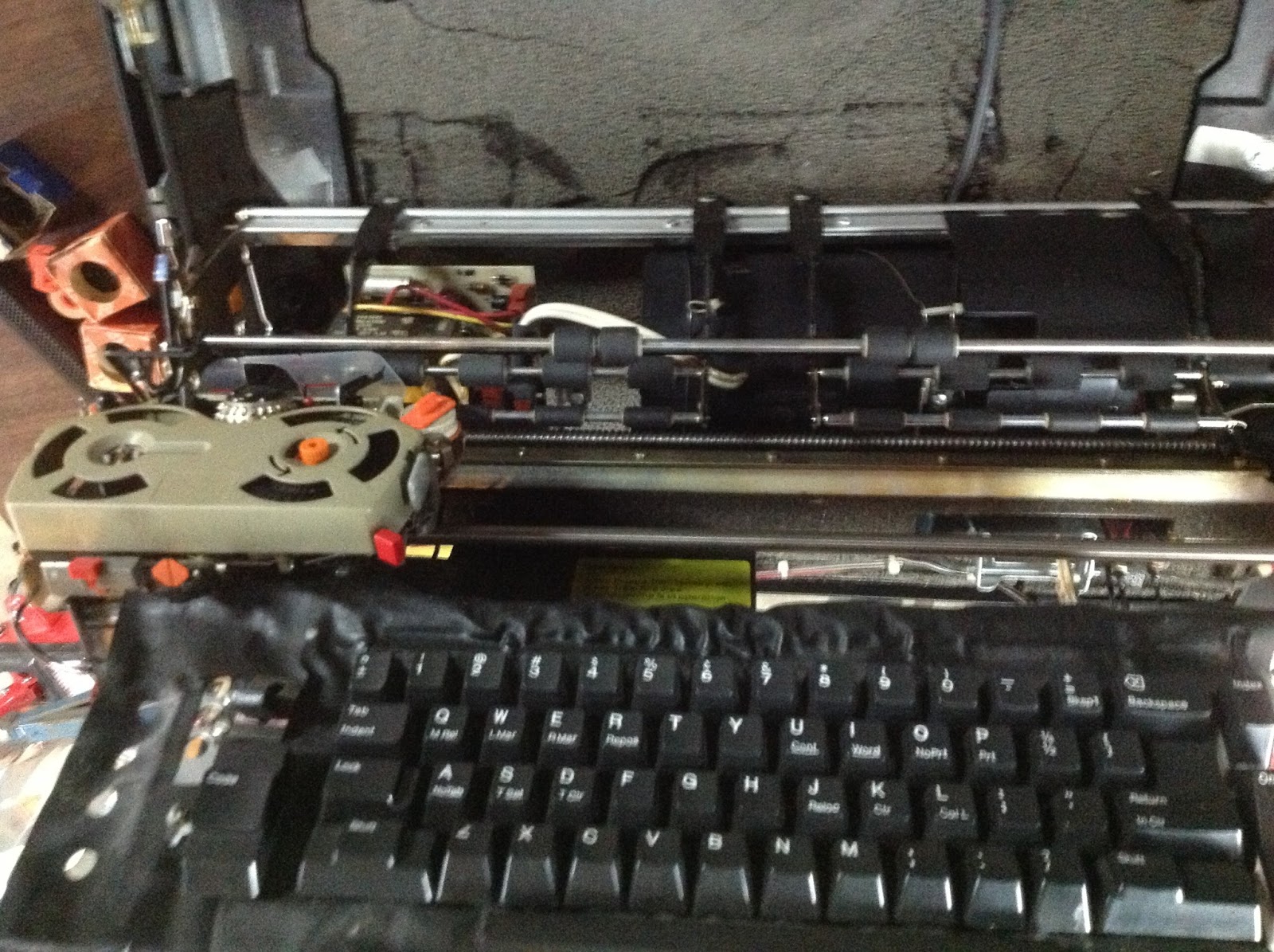 |
| Electronic 50 has keys separated from print mechanism |
 |
| Seolenoids and circuit board in Electronic 50 Selectric |
However, two issues remain that must be overcome. First, the typeball used on the E50 is incompatible with the Selectric 2, featuring more character positions to cite one difference. Thus a typeball from an 1130 won't work properly. As I hoped to find an APL typeball and run 1130 APL on my replica, this will be a barrier. Second, the microswitches and means of reporting the rotary position during operation of cycles, such as a basic print cycle, are different. Optical pulses are sampled by the circuit board in the E50, rather than microswitch contacts being activated. My interfacing my require some custom microswitches or an adapter circuit to convert to the kind of feedback signal expected by the 1130 console printer adapter logic, which believes it is connected to a 1053, not an E50. I may need to produce one or more custom typeballs or translate tilt/rotate codes on the fly in order to produce the intended printed characters from the E50 typeball.
The IBM solenoids operate at 48V, requiring me to design and build a circuit card taking 3.3V logic inputs and activating the solenoids with 48V at sufficient current to work properly. That is still in design, but I will build a prototype board shortly to begin testing the integration of the E50 into the 1130 system.
Testing the prototype of the console hw - part 1
The display light panels were formed using LEDs in the final pattern that will be illuminated behind a plexiglas panel in the pedestal unit that sits above the console printer on the IBM 1130. These were cabled to the display drivers, fanout logic, concentrators, switch debouncers and data links, which were attached to the FPGA 1130 and tested. Switches from scrap panels of IBM 3420 are used, along with toggle switches for the Console Entry Switch group temporarily mounted on a cardboard rectangle, and a rotary switch to be used for the Mode switch on the pedestal were wired in to test actual hardware components intended for the replica 1130.
The keyboard and console printer elements are not yet ready for testing, although temporary logic is provided to allow a PS/2 keyboard to be used for entry. The key layout is matched, but the keycap markings, shapes and colors are not the same as the 1130 and the feel is completely different. It will allow debugging and use of the system until the final keyboard mechanism is constructed. Similarly, emulation is provided for the IBM 1053 device used as the console printer, emitting ascii over the fpgalink to a PC which will display what is being 'typed' by the console device. These two emulated portions will be tested a bit later, followed by prototype testing of the final designs once my keyboard and printer hardware is ready.
 |
| Prototype of light panel being constructed |
 |
| 1130 Pedestal Light Panel |
The buttons and lights near the keyboard will be similar to these, although mined from scrap 3420 tape drive and scrap buttons found on ebay. These are wired through the debouncer to the concentrator.
 |
| 1130 Buttons and Lamps near the keyboard |
 |
| Scrap 3420 panel to provide buttons and lamps |
The keyboard itself is repurposed from the 029 Keypunch, and that would be the first choice if I can get my hands on a keypunch or the parts, otherwise I will need to come as close as possible.
 |
| Keyboard of the 1130 (or 029) |
The Console Entry Switches go through their own concentrator board, one I received from Richard Stofer, wired to some toggle switches bought on ebay. These are not an exact substitute for the 1130 switches but are very long toggle handles to permit mounting in a realistic setting in front of the console printer.
 |
| 1130 Console Entry Switches |
 |
| My CES prototype with R. Stofer's board |
Once the switches are mounted in their more permanent location on the console printer faceplate, this will be fully usable.
The test setup with the console display lights hooked into the 1130 - not working properly initially, recoding along with testing to fine tune. Didn't put enough capacitors protecting the + power to the board, to avoid the impacts of all the current switching into and out of the LED array. This removed glitches to yield a much more reliable transfer to the MAX7219 chips. Found a few bad LEDs, some broken wires in the harness and a few unsoldered leads on my prototype board. Cleaned up and moved on to debugging the displayed state of the lights. There are still glitches occuring, thus more work needed on the prototype board, as well as some wiring issues remaining in the right hand board. Progress is steady, however, and it is only a matter of time before this is solid enough to consider the design final. At that point I will design a production printed circuit board and build it.
 |
| Testing the light display panel hardware |
The button and switch entry unit were debugged, then tested with the 3420 tape unit buttons hooked through the debouncer board to the multiplexor board, whose link worked well with the console link function inside the fpga. Work is now underway to design a final printed circuit board for the button/switch entry logic, merging the debouncer and multiplexor boards into one. This will be fabbed by an outside service and then components soldered on after I receive the board.
When the production version circuit boards are built, I will conduct a second round of testing/debugging of the completed system.
When the production version circuit boards are built, I will conduct a second round of testing/debugging of the completed system.
The Search For Authentic Hardware
With realism of the experience for a person using the 1130 replica as a key objective, it was important to recreate as much of the system as reasonable. That is one of the reasons to build a physical panel with the blinking lights at full size, as well as the rationale for using a Selectric typewriter mechanism for the console output. This entry describes the process of acquiring and/or building the appropriate parts of the machine.
Scrap parts for some mainframe systems are still plentiful in the used markets. IBM tape drive units are particularly active on Ebay at this time, where the operator panels include the same kind of switches and lights as are used on the 1130 - plastic rectangles in red, green, and blue for the pushbutton switches and rectangular plastic blocks in white, yellow, red and green for the lights. Some of the buttons are usable as purchased, for example the "Start" and "Reset" buttons, but others will need the wording altered to match the 1130.
On the console pedestal, alongside the blinking lights, are a rotary mode switch on the right and a red emergency pull switch on the left side. I found a suitable rotary electrical switch to actuate the mode switch, allowing selection of 'single step', 'single storage cycle', 'single instruction', 'normal', 'interrupt run', 'load' and 'display' modes. I am using a scrap part knob from a different IBM mainframe to make the mode switch appear as accurate as possible. The emergency pull switch is a problem, even though it will not be operational, because it is so iconic for IBM mainframes. These are apparently highly prized souvenirs and extremely difficult to find. At this point, I expect I will be building a replica to install on this 1130.
I have described the challenges of converting a Selectric typewriter mechanism to server as the operator console, but a brief discussion of some additional factors is warranted. I used Craigslist to pick up a Selectric II, bought solenoids from an electronics supply house, and then bought an Electronic 50 as that is potentially easier to convert. However, the mechanism is housed differently, since there is no typewriter keyboard on the 1053 console printer. I will modify or build a housing that matches the 1130, place it around the converted typing mechanism, and integrate the tabs/carriage indicator. I will need to add a rocker for tab set/release, as well as button switches for Tab, Space and Return. Finally, the front of the printer also features 16 white tipped, silver handled toggle switches called the Console Entry Switches. I bought large toggle switches with extended handles, but will need to convert the ends with white caps to match. Most likely, I will grind down the ends to a stub cylinder, then glue on a white plastic cap that I make with a 3D printer.
The keyboard is a mechanical device with the unique heavy feel of the 029 Keypunch whose mechanism it leverages and the unique key layout and key shapes. I am currently trying to buy a very similar keyboard on Ebay, which is photoelectric not mechanical but otherwise identical in appearance and layout because it was built as part of a keypunch system. The initial price was just too high for the realism it provides ($350 plus shipping), especially because I can't feel the action of the keyboard in advance and don't know if I can implement the interlocking and need for a reset key to release a 'jammed' situation. I sent emails to the seller offering a lesser amount, but the buyer has not deigned to reply, although it was relisted a few times and reduced to (a still too high price of) $299. After the last auction elapsed, I emailed one final offer of $200, probably way too much but I am still receiving deafening silence from the seller. Sometimes people have firm ideas of what they believe their goods are worth, in spite of continued market evidence to the contrary, and they become offended by any suggestion of a lower price, not even bothering to counteroffer.
The fallback is to create a keyboard using mechanical switches, some foam or other material to increase the keystroke resistance, and some method yet unknown to create the lockout (jam) condition. Another alternative is to separate the keyboard portion of the electronic 50 typewriter, which is already fitted with microswitches, and make use of some form of that as a mechanical keyboard. This would certainly provide the interlock and need for a solenoid to release 'jams', but requires custom keycaps and may be difficult to map exactly to the 1130 keyboard layout. More research will be needed.
The tabletop will be wood with white laminate, similar to the actual 1130 table, but not full height off the floor. Instead, it will look as if someone had used a chain saw to cut off the top of an 1130, leaving just six inches or so below the lowest edge of the tabletop. The metal portions will be copied, as these are all painted and can be replicated pretty well - pebble finish except for the plate atop the keyboard which is smooth - and in authentic colors.
I have access to real 1130 systems at the nearby Computer History Museum and also at a nearby private collector's home, allowing me to measure more accurately, test coloring and finishes, and test out the keyboard action. The CHM machine can't be touched, although I might be able to arrange permission using gloves, but the collector's machine is going to be fully accessible. I would like to check out the intensity and behavior of the lights on the pedestal console display, and to record the noises of the 1130, but neither of these machines are powered. There are two powered machines I might get access to for the light investigation and recording - one nearby at a second private collector's home and the other near London in the UK at the National Museum of Computing.
I am producing peripheral replicas as possible - paper tape, plotter, card and printer devices are all possibilities. Initially the plotter is handled by a clever unit built by Richard Stofer that converts the plotter instuctions of the 1130 adapter into HP-GL commands over TCP/IP, allowing it to drive any HP-GL compatible plotter or printer. If I buy a plotter that could be forced into a replica housing, I might be able to produce the 1130-like plotter, but at worst it will be used to link to a HP-GL compatible laser printer.
I have bought a paper tape reader mechanism on Ebay (it was how I came to meet one of the private collectors in the area) which I will fit into a replica housing to look like the 1130 peripheral. I bought the punch block for a teletype - the dies and fitted holes that are driven to punch holes in paper tape - which I only need to fit to solenoids and install with a sprocketed driving mechanism in order to build the paper tape punch. If this pans out, I will also need to buy some blank paper tape stock on ebay.
Punched Card equipment is in short supply, but I may be able to create some form of punched card input/output. There are occasional readers or punches appearing on ebay - right now there is a duplicator (both reading and punching plus the card transport capability) but the offered price at $495 is a bit high since there is no guarantee it is in working condition. I have a mechanical keypunch (Wright 2600) and a box of 2000 blank cards, both bought on ebay, thus I could move forward on the reader/punch if I choose.
Line printers are difficult to build as a replica, mostly due to the lack of continuous form paper supplies. and the fact that chain or wheel based printers have long been replaced by other mechanisms like laser printers, but the right basic mechanism might show up somewhere and trigger a subproject.
Disk IO on the 1130 uses the 2310 mechanism and the 2316 disk cartridge. Used cartridges are found on ebay periodically, but not the drive mechanism. However, several other makers built similar products, including DEC (RK-05 disk), Pertec, and CDC, any one of which could be pressed into service. The unique 'grunting' sound of the actuator might need to be reproduced, since the mechanisms for seeking and positioning are different on the compatible drives, but many options exist. First, I could put flash memory inside a disk cartridge along with zigbee or similar wireless, allowing the cartridge to be placed into a mock disk mechanism and accessed - playing some simulated disk sounds as it operates. I have bought an IBM 8" floppy drive mechanism as it seems to use a mechanism most directly derived from the 1130's disk, thus it might provide the right grunting sound. I could use a floppy itself as the disk cartridge, or just use that part of the mechanism for authentic sounds - more investigation and design work is needed.
Other peripherals such as the 2250 graphic workstation, optical mark reader and alternative readers and printers, are not in scope at this time.
Subscribe to:
Posts (Atom)