I did a quick run on the CNC waterjet cutter to make the holders for the buttons and lights. However, I made a small error in calculating the relief room needed in the button holder metal that will sit under the black plate, into which the lamp and switch holders are snapped. It resulted in too much vertical spacing between lights/buttons by a factor of 3/32". This has to be corrected so the buttons and lamps will stick up through the black plate.
Techshop and Autodesk offer a six month free use of the entire Autodesk Professional suite on my home computer, which will be very handy as I create and edit the design files that drive all the CNC machinery. I installed it Monday night and began working on files the next day. I fixed up the cutting files for the button holder plates and ran them off on the waterjet cutter on Wednesday. Alas, I still had a flaw in my layout and had to make another run on Thursday. With that done, I test fitted the switch/lamp housings and all was good. A quick set of bends on the sheet metal brake Friday, a few holes drilled, and the lights and switches are installed in their final position.
I carefully installed all the pushbutton switches, as these require a trick to get them installed on a panel. The pushbutton switch component won't fit through the openings, so it has to be added after the plastic holder is snapped into place. However, the switch sticks out at right angles for 7/8", thus it can't rotate to fit into the threaded nut since the switch will hit the switches next to it on the holder. I have to drop all the switches out of the snap position, so they are resting on the switch component, leaving room above them for the one switch I am installing to swing around if its holder is the only one snapped into position.
With these in place on the latest set of button holder plates, I measured the vertical gap between the button holder plate and black plate that is needed so the IBM plastic button/light holders fit snugly against the bottom surface of the black plate. That allowed me to design the mounting hardware, fabricate it and install everything on the assembly.
The black plate itself has one flaw - my cutaway for the keyboard is not correct in the location where the "A" key sits. The metal is 3/16" too far to the right, impinging on the keycap. I took the plate to the shop on Wednesday and milled away the extra metal, then shot a bit of spray paint to hide the metal edge that is revealed. My mounting brackets hook the black plate to the keyboard mechanism, with the entire assembly sitting on steel flats I installed on the frame.
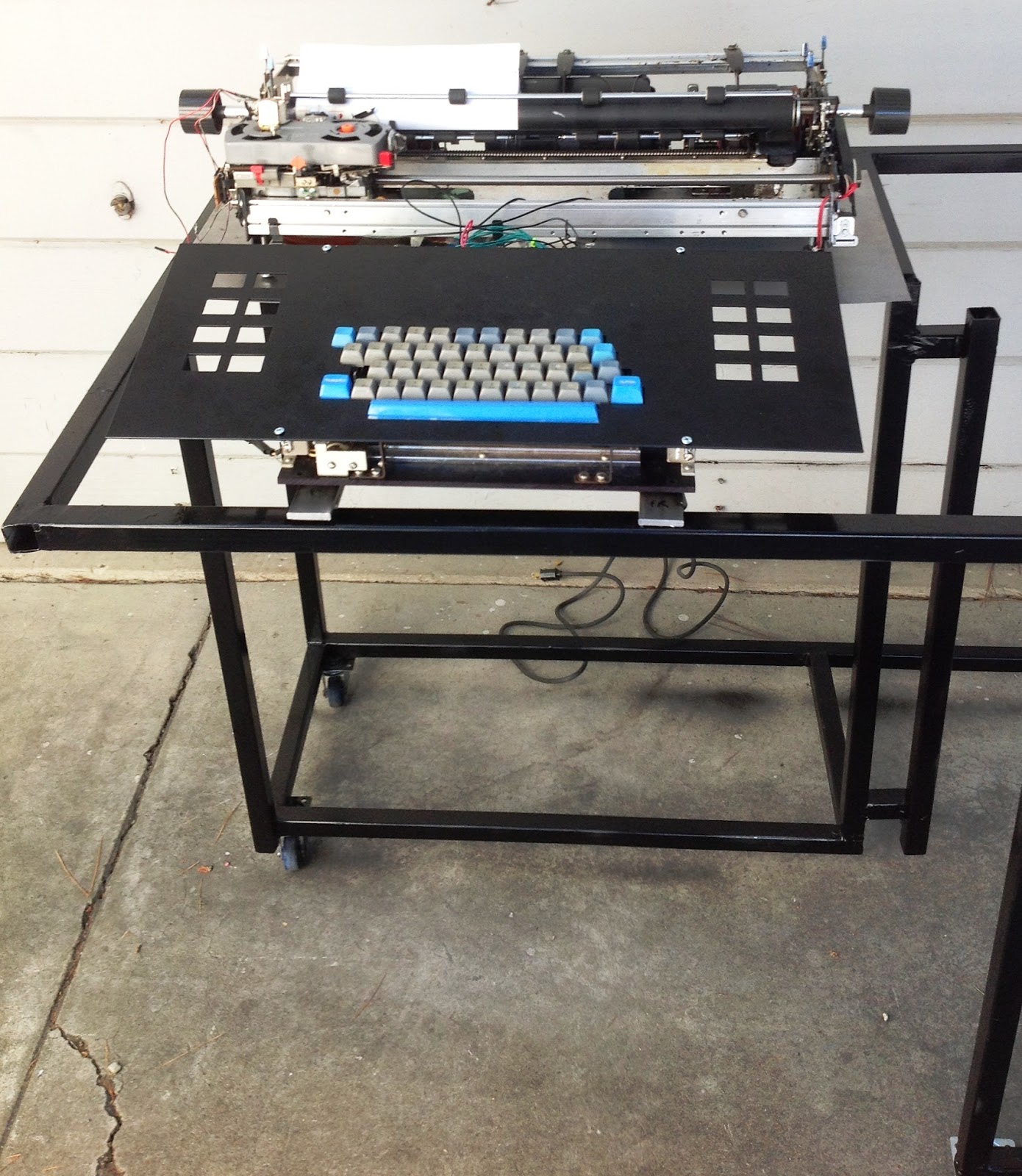 |
| Keyboard assembly and typewriter sitting on the frame to do measurements |
TYPEWRITER MOUNT AND ENCLOSURE
The typewriter needs to sit about 3" higher than the keyboard/black plate assembly and I have the challenge of producing an enclosure for the typewriter since my mechanism is several inches wider than the unit used in a real 1130. Also, the platen (rubber cylinder on which the paper rolls) is more than 2" further forward than on the IBM IO Selectric used on the 1130, so the knobs will be more forward on my machine. These differences will distort the alignment of the various parts - the real 1130 has things aligned like the black plate edge, the plate on the front of the typewriter, and the display plexiglass on the pedestal above the printer.
I had to produce a design that looks like IBM built it but adapts to the wider typewriter enclosure. IBM had a process for customized features on machines and called those nonstandard features RPQs. I think of my machine as an RPQ version of the typewriter for the 1130, as if a customer requested a wider carriage on the console printer. I imagine this is how IBM might have delivered this RPQ feature. In one way, this will look better than the 1130 - the typewriter knobs will now be centered front to back on the enclosure, where in the real 1130 they are one of the few asymmetric features on the machine.
MAIN DISPLAY PEDESTAL
The stands and pedestal box flaws and bumps were filled with JB Weld, an epoxy that contains steel. It can survive temperatures up to 450 degrees, and the steel inside gives it conductivity for the electrostatic charge that will cause the pigments to adhere, thus it is compatible with the powder coating process I use.
I mounted the stands after sanding them flat, soldered on mounting plates inside the box that will be used to hold the Emergency Pull and Mode Switch plates onto the face of the pedestal box. With the back plate screwed into position, it was ready to be prepped for powder coating. I took it Thursday to the sandblaster cabinet and created the right surface texture for best powder adhesion.
Friday, I booked the powder oven, stripped the box and its parts of any oil or dust by a good chemical washdown, then sprayed it with iron granite metallic (gray bumpy texture) powder and baked everything. I selected the powder from the online catalog as it appeared to be close to the finish on the IBM 1130 (gray color on their sheet metal enclosures).
The color and texture match is not perfect - it is too glossy and metallic with rectangular texturing whereas the IBM color is a flat gray with a sandy pebbly feel. Also, I had some problems due to the size and awkwardness of the pedestal plus stands - it was so unwieldy that I bumped it a few times during the process - leaving some imperfections in the finish. They don't appear too noticeable; I will move forward with this version of the pedestal.
I prepared the hollow aluminum tubes that hold the main logo plate atop the pedestal box, by drilling it out to allow a threaded 10-24 rod to fit. The logo plate has 10-24 threads tapped into the bottom, and the rod then extends through the aluminum tube and into the top of the pedestal box, where a conventional nut on the inside secures the logo plate in position.
I am adjusting the holders to allow the two side plates - the emergency pull knob and main mode switch plates - to be held in the correct position on the face of the pedestal box. The plexiglas panel fits between those two side plates. I intend to glue on friction fit springy metal on the sides of the plexiglas, at the rear, so that it can be snapped into place and removed from the front.
TABLETOP SURFACE
The tabletop for the 1130 is a 59" wide and 14 1/2" deep white formica covered wood surface, in my replica it will be about 5/8" thick but on the IBM built machines it is 1". The tabletop slopes upward at an angle of 11.5 degrees, going from front to rear, with corresponding adjustment of the front and rear faces so they are at right angles to the ground. I will build this from a single 48" x 48" board of MDF, 1/2" thick, cutting it into two 29.5" x 15" boards that will be held together as a single long 59" table by several metal straps on the underside. These boards will have white formica glued to the top surface after machining.
Using the CNC wood router at the Techshop, I will mill the slanted front and rear angles, reducing the boards to their final 14.5" depth, and then cut the opening and wider inset for the black plate. With those done, I will return the two boards to my home shop to strap them together, then glue on the white formica to the top and all four sides. Using a hand router, I will trim away the formica that is covering the routed opening where the black plate will sit. The edges of the opening will have been painted flat black before the Formica was added.
The tabletop attaches with front hinges so that it will open upwards from the rear of the tabletop, pivoting along the front edge of the machine. A brace on each side will hold the plate and keep it from slamming shut whenever it is opened.
I reserved time on the big CNC router but found that my design files were done at home in Autodesk Inventor 2014, but the techshop systems are still on the 2013 version. Nothing could read the files I designed and I wasn't able to recreate everything fast enough to get use from my timeslot. I surrendered the remaining time to allow someone else to use it. I will work out a way to create downlevel files and use these on my next visit to use the router.
I was able to reorganize my garage and sheds, to make enough room to get my woodworking equipment usable to cut the wood down to nearly its final size. This will make it much easier to handle and to achieve the final cutting of the opening and recess. I did a save of the cutting path as a DXF file in older format, which should be readable by VCarve Pro or Cut3D which is what I will use to produce the toolpath for the cuts.
Finally on Sunday I found some time on the midsize CNC router and carved out the opening for the keyboard. I have a tiny bit of cleanup to do on the inside recess into which the plate's edges are hidden.I also have to trim the far end, nominally 59", to fit exactly on the sheet metal I am installing on the frame.
UPPER SHEETMETAL WORK
The front half of the machine top is a tabletop sitting on a slanted metal 'box', , the table being about 2" high in the front and angling up at 11.5 degrees to be 4 7/8" high at the midpoint between front and back, right where the typewriter face sits. The back half, surrounding the typewriter, is a flat box that is 4 7/8" high on the sides but dips to 2" high for the left to right section where the typewriter enclosure sits - a recess for the typewriter.
These were designed with the sheetmetal functionality of Autodesk Inventor, then cut and bent at the Techshop Friday and over the weekend. First up was the back half on which the typewriter enclosure will sit, as well as the base into which the display pedestal stands are connected. It has a mix of "forward" and "backward" bends, which can't all be done on the sheet metal brake. I completed all but one bend through a variety of tricks and took the metalwork home. There I will complete the last bend, solder up the seams and fill one spot with a small flat plate. Once that is done, I will fit this to the frame, notching cutouts for various places that need clearance, drilling and mounting it.
It was challenging to make the last bend - I had to figure out a method involving wood and metal slats clamped onto both faces of both sides of the bend, then apply the pressure through the clamped slats. It is hard to get a crisp bend, the metal tends to form broad lazy curves. The thin metal slats had to be rigid enough to apply pressure, yet sharp enough to encourage a sharper bend. I inserted a long wood form around which the bend will be done, clamping a very rigid metal plate on the outside. I then hammered the bend into place with a soft rubber mallet. The result is pretty decent, not too much distortion.
I marked up the places where I had to remove a bit of material, because of interference with the frame, then after cutting out the excess, I installed each piece carefully, drilling holes and screwing it to the frame, doing some bending, twisting and finessing to make everything line up and look good.
A few others were finished on the weekend. Once they are all fitted and all their seams soldered, they will be brought back to Techshop for powder coating in the iron granite metallic finish. There are two pieces left to make, one is the right side of the stand sitting under the tabletop, and the other is a replacement for the typewriter stand sheetmetal. First, it is too short to meet the right rear sheetmetal, Second, it isn't high enough to be flush with the tabletop when it is installed. Third, my mistake with the bends leaves it a bit funky looking. I adjusted the design and am ready to cut and fold them next week.
DECAL PROCESS BREAKTHROUGH
The owner of the firm making the decal process kits has been working with me as I try to figure out what was going awry. At one point he steered me in a direction I hadn't suspected - that the paper was not being adequately dried out by the hot air gun step, thus it was shrinking during lamination, wrinkling mylar films and spoiling the bonding.
The hot air gun I have is one I bought for my wife's craft projects a year ago. It is a low quality unit sold by Harbor Freight and other retailers under the brand name Drillmaster. Although it claims to operate at 1500 watts, I suspect it is putting out way too little heat in spite of all the noise of the blower. These 'paint stripping' air guns should be emitting air at about 1,000 degrees. When I read through various web customer feedback on Amazon, Harbor Freight and other websites, failure of part or all of the heating elements was extraordinarily common. Most likely that happened with this one, leaving only a sliver of working element.
I picked up a new hot air gun at Lowes and did another run of the decal process. Superb results. No wrinkling at all on the first lamination step where the colored mylar film fuses onto the toner (black portion of image) on the paper. Excellent transfer of the fused mylar onto the clear carrier mylar in the second lamination step, although due to an attempt to skimp on the size of the carrier mylar (actually to not have to cut another piece), I got some slight wrinkling. Even with the wrinkling, the fine lettering stuck perfectly to the carrier mylar when it separated from the paper backing in the water bath step.
In anticipation of this, I had ordered some extra white and black mylar films, since most of the text I will be transferring for the 1130 project is in one of those two colors. All was set for some production runs this weekend, spewing out decals for the mode switch, emergency pull knob and for the display pedestal plexiglas panel.
Alas, when I attempted to fabricate those four decals, only one was close to usable (but not enough). Three of the four suffered extreme break-off of the image in the water bath, just like before. The last one lost parts of letters at the beginning and end of a phrase, but the rest adhered well. I am not sure what differentiated the last decal attempt from the other three, which means I won't know what do to more of, or less of, to get to success.
Saturday night I attempted six decals and had abysmal results - the step where the clear carrier mylar is supposed to adhere to the image does not work right. I will give this one or two more attempts, then speak with the maker of the system.
I seem to be able to get decent decals by sliding the materials into the water bath in a way that intuitively seems to be wrong. That is, the paper has a curl and you slide it in to allow the paper to curl into a tight scroll in the direction it prefers. However, when drying the paper at the beginning of a fab step, you observe the curl tendency and that is different from the way the paper curls in the water.
I believe this is a result of the laser printer I am using - a Brother HL-2170W - which puts a curl into the paper as part of the heat of printing. That curl direction is at right angles to the "natural" curl preference of the paper when I dry it. In the water, the paper tightly curls the way the printer has conditioned it during printing. If I slide it into the water with the first edge touching, the left or right side of the image, being parallel to the axis of curling, it forms the nice tight curl. The image breaks off, however, and is unusable.
If I insert the top edge of the image, the "natural" curl direction that is exhibited during the drying step, then it twists and immediately goes into the same type of scroll it did with a left edge entry, but the paper relaxes faster and the mylar floats off soon with the image intact! I produced two successful decals in a row, then shut down for the evening. Next week I will create all the other decals I need, ensuring that this success is not a temporary fluke.
TYPEWRITER PLATEN KNOB FABRICATION
I intend to make authentic appearing knobs for the console printer (typewriter) by milling an aluminum mold for use with the injection molding machine at Techshop. I will find some ABS or similar plastic in the light blue IBM used, something like a Peacock Blue shade. This plastic is also useful for the buttons on the front of the typewriter (return, tab and line feed) and for the handle on the internal disk drive, although I would need two additional molds to build the buttons and the handle.
The Autodesk Inventor software has all the functionality built in to help me do this. I first build a 3D file representing the plastic part to be manufactured, then go to the mold creation module. That module will create the inverse shape as a mold, allowing me decisions about where to split the mold, what kind of channels I use for even flow of the plastic and other design details. It will then simulate the use of the mold and provide feedback about uneven flow or other issues. Iteratively, I can hone the design on this software.
Next, its integrated manufacturing capability will generate the CNC milling instructions that will create my mold using the Tormach PCNC 1100 at the shop. Once the mold is done, I have some intensive polishing to do for the face of the knob, to make it as smooth as the one on the 1130. This involves careful sanding with very fine grit sandpaper similar to how a show car's finish is polished to a glasslike appearance.
The actual manufacturing of the knobs is the easy part - about 30 minutes maximum to set up the machine and heat my plastic stock, then about five minutes per knob to stamp them out. I designed a threaded hole for a setscrew to match the system used on the ET50 typewriter. Its platen rod is a square cross section out at the ends where the knobs attach.
I have the knob almost completely designed already, but the edges of the knob have a kind of knurled surface to help the operator grip the knob. So far I haven't figured out the magic incantations to cause Inventor to place them on my design. The surface getting the 'knurling' is slanted, connecting a gentle arc on the outside with the flat circle of the inside, and I can't find a way to select this surface to tell Inventor to emboss or cut the slots.
As of Sunday night, I worked out a way to get the knurls on the knob, but they are now all the way through the bottom, when I need them to end about a sixteenth of an inch before the bottom. If I can figure out the last bit, I can move on to designing the mold itself.
No comments:
Post a Comment