I bought some white Formica laminate to glue onto the tabletop, wrestled the 4+ foot by 8+ foot sheet into my SUV and brought it home. For some reason, any time I buy Formica and am leaving a store with these huge, fragile and flexible sheets, strong wind gusts strike, whipping the expensive laminate sheet around as I fight to get it to my car in one piece without cracks or worse. Fortunately, I won this battle and got it into the SUV in one piece. Once I set up some horses in my driveway and stuck a board under it, I had a good platform to cut it down to manageable size - about 18" by 60".
With it cut to rough size, I cleaned up the surface of the tabletop, swabbed on contact glue and placed the laminate under some boards to apply suitable pressure. The next morning, I trimmed the edges using a router with an appropriate bit. As well, I plunged the big down into the keyboard opening and then trimmed around that rectangle.
The slanted front and rear edges created a bit of a challenge trimming with a router bit, which normally has a bearing ride on the flat surface while the cutters trim any excess at the top or bottom. With a slanted surface, this won't work. I tried using an aluminum channel as a reference edge to run my router along, but got some flex in the middle of the 60" run that chamfered the edge - messing up the part. I was able to run it through the table saw to slice off a very tiny bit at the same slant angle, still leaving an acceptable gap at the rear when the tabletop is in place. I have a very high quality blade designed for laminates and similar materials with 84 teeth per inch, cuts through the material like butter with zero chipout.
 |
| Gluing up the laminate front and rear strips - notice 11.5 degree slant of edges |
The result looked very nice, ready for hinges to be applied and the tabletop mounted in place. There is an aluminum bar mounted to the table surface, used to keep papers from sliding off the slanted top, which I have to create, tap and bolt on.
FITTING PARTS OF THE MACHINE
I have been fitting together various parts of the machine to make sure they fit properly, verifying clearance and making adjustments to get everything lined up well. So far, the major elements are going together as expected.
 |
| Fitting process,ensuring clearances,proper fit and alignment |
 |
| Another view of interim fitting |
I begin milling the emergency pull switch on Monday, roughing out the shape of the stem and the angled back on one of the lathes at the shop.
 |
| Stem and rear of emergency pull switch are roughed out of the aluminum blank |
What remains to do:
- finish cut the stem and back
- use a horizontal bandsaw to cut the front of the knob from the large diameter aluminum blank
- chuck the stem into the lathe and surface cut the face of the knob
- mill an inset region in the face, leaving a 1/32" rim
- thread the end so I can bolt it inside the pedestal box
- prime the inset region of the face
- paint the inset region with a red paint
- apply the white lettering decal I fabricated
 |
| Sticky side of decal to apply to EPO knob face |
 |
| Visible side of white text decal for EPO knob - in front of random red object |
DECAL PROCESS IN PRODUCTION
The decal system I am using for lettering is debugged and I am getting good results now. I discovered that another problem that could be affecting me was the use of a Brother laser printer, due to an unsuspected incompatibility between the decal process and the unique toner formula used in the Brother printers. It was not documented on the decal web site, but mentioned by the owner of the firm in an email to me. It seems that the printer brand uses a higher temperature epoxy in their toner, which causes some problems with fusing of colored mylar to the toner, a problem I appear to not experience, but likely the higher temperature used in the printer is causing the odd curling of the paper.
I took my images to a local Fedex-Kinko center and had them print on the special paper. The strong curl didn't occur, the paper was essentially flat after printing, and the entire system worked flawlessly as a result. I have completed the decals for the plexiglass on the display pedestal, for the emergency pull knob and for the mode switch.
I am now producing the remaining decals to relabel light blocks, push buttons, toggle switches, keycaps and logo plates. These should be all the remaining requirements for text for the machine. I did this in several blocks - as some of the text is black colored and some is white colored (to place on dark surfaces).
As an alternative I made paint masks from black acrylic using a laser cutter, potentially to use with both the plexiglas display panel and the mode switch, if I didn't get the decals transferred on with acceptable quality. The main challenge with the acrylic mask is that the "centers" of letters fell out - the inside of an "o", for example. I made a vinyl mask of the same content and will try to pick the centers from the vinyl and put them down in place to 'fix' the acrylic mask, if I ever need to master that backup method. For the time being, the decal system is my main workhorse.
The system is Decal Pro FX and it produces dry rub decals. These leave only the colored image on the target surface, no thin plastic covering like the wet decals familiar from plastic toy model building. It uses an ordinary laser printer to create the image in black and can make decals of the image in a wide variety of colors including white. Web site of the decal system
The owner of the business worked with me by email and on the phone to sort out the problems I was having, which shows how confident he is in the quality of the process and how important customer satisfaction is to his company. I can enthusiastically recommend this system to anyone needing to produce high quality decals, lettering and images.
DISPLAY PEDESTAL PANEL FABRICATION
I applied the mode switch decal to the right side plate, mounted it and the left side EPO plate. Next, I began to fabricate the plexiglas panel. The first step was applying the decals with the titles of the registers and status blocks. Next, I layered on light gray over and around the text, darker gray where the lamps will show the value of the register, then a full coat of black behind it all.
This sandwich must have some of the paint etched away, allowing lamps to show through. For each bit position, the etched shape is the characters of that location - in other words, bit 14 has "14" etched away, bit 0 has "0" etched, T4 clock state bit has "T4", and so forth. This leaves a transparent space in the shape of those characters. I used a laser cutter at the shop to etch away the paint.
Here are some pictures of the various stages of the panel fabrication, showing how it was created and the end result:
 |
| Plexiglass cut to size - protective sheet on top to avoid scratching |
 |
| Decal sticky side for panel left side text - flaw in letter 'c' in "factor" |
 |
| Two versions of decal for panel right side text, each with some flaws |
 |
| Layers to be cut, adjusted and applied to plexiglass |
 |
| Some layers stacked to illustrate how they combine under plexiglass |
 |
| IBM made 1130 panel that we are reproducing |
My first attempt highlighted some process problems I have to address. It is way too easy to lay down the decals crooked or out of alignment, which ruins the attempt. I will try putting the carrier down on the jig, then the plexiglas laid on top. To guide the plexiglass, I will tape down wood slats to force the acrylic to drop in only one spot.
Another problem I flushed out with my first attempt is that the application of the first vinyl mask has a sticky paper holding the bits in alignment, but that sticky surface will touch the lettering through the 'holes' and pull away the letters. The fix is a combination - leave the lettering to dry for at least an hour and carefully cut the sticky paper away from the holes before applying the vinyl. If that doesn't work, a third step of applying a clear gloss paint coat over the letters may be required.
Finally, I discovered that my vinyl paint masks have incorrect spacing between the third and fourth rows, being about a 16th of an inch too far apart. This is incompatible with the decal spacing and with the LEDs. I will need to correct these mask files and recut them.
However, I did a trial with the jig of wood slats, spraying adhesive to put the decal in position into the jig, then dropping on the plate and rubbing. Excellent transfer and exactly on target. Now, once my replacement stock of transfer paper arrives this weekend, I can print up new final text decals, as long as I have cut the new vinyl paint masks at Techshop first.
TYPEWRITER ENCLOSURE DESIGN WORK
The Electronic Typewriter Model 50 mechanism will be covered with an enclosure similar to the one on the IBM made 1130, although it has to be a bit different to accomodate the physical differences from the IO Selectric mechanism they used. My typewriter is 5" wider, which affected the enclosure, the upper sheet metal and many other aspects of the machine.
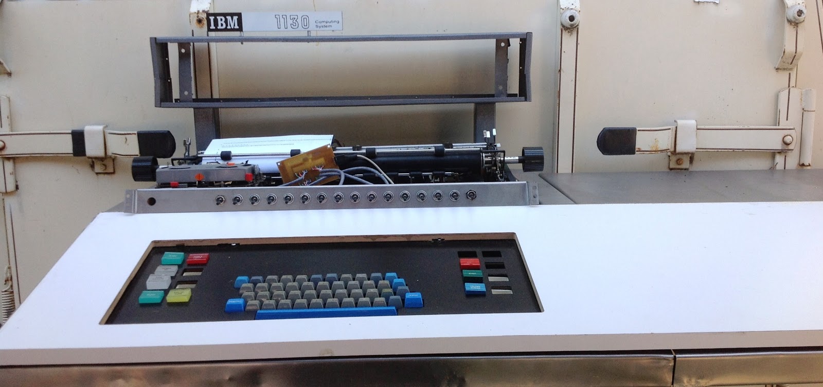
I was finally able to find a source for the switches used on the front of the typewriter - the console entry switches - that allow the operator to set up a 16 bit value to be read or loaded into a machine register. The only difference between these switches and the ones on the 1130 is the color of the tip - the 1130 has a white plastic tip while mine have tips that are black. I will look into a way to dye or paint the tips white.
 |
| My console entry switches to mount on the plate at the front of the console printer |
All these parts behind the black plate must not interfere with the movement of the typeball carriage inside the enclosure, yet allow the pointer for the current character position to be visible in the plastic ruled scale. The platen knobs must be free to turn, without touching any external sheet metal. The pedestal display stands have to fit behind the wider and deeper enclosure.
Just as importantly, the changed positions and design must look appropriate and consistent with the design approach and esthetics of the IBM 1130. The black plate on the typewriter enclosure lined up with the plexiglas display panel above it, both being roughly 20" and the main black plate in the tabletop with the buttons and keyboard is also about 20" wide. My wider plate must seem to line up with other features and the stretched proportions must look natural. For example, the console entry switches are spaced 3/4" apart on the 1130, while my design will space them apart by 1". This keeps the ratios consistent across the black plate.
I am building all the files in Autodesk Inventor, using them to create CNC files for the waterjet cutter, and thinking through attachment and mount details. It will probably be another week before I am done with the design work and able to begin fabrication.
However, I was pretty confident that the switch holder plate is 'final', so I got on the waterjet at the shop and cut it out. The 16 console entry switches are now in place and working properly.
 |
| Console Entry Switches installed on their holder plate |
 |
| Design of platen knob, not yet complete |
USAGE METER PANEL DESIGN WORK
The 1130 was rented to customers, with a usage meter that ran when it was running but stopped if it was idle or powered off. The top of the machine, to the right of the display pedestal and console printer, had a black plate set into the top with two hour meters and a key switch in between. One meter was used to bill the customer, but when the 1130 was being serviced or checked out by the customer engineers from IBM, they turned the keyswitch and accrued the time on the other (CE) meter.
I have two similar hour meters which I will install on a plate made to look like the 1130's version. This will sit in an opening of the upper rear sheet metal, visible looking down from in front of the machine. My plate will be mounted to the frame and sit hard up against the upper rear sheetmetal box, which will have an opening cut to match the usage plate outline (but slightly smaller).
 |
| Usage meters to be installed in metering plate |
I may activate the usage meter, as these are easy to do by detecting the run light signal, but it is a finesse I have not yet decided upon. At least visually, they will be in place, but perhaps not functionally. The 1130 has some circuitry to integrate all short term run and wait conditions and to set minimum durations before changing the meter from running to stopped or vice versa - copying this behavior would require me to output the meter run signal itself, something I had not designed into the system yet.
No comments:
Post a Comment