The original plan for this system was to make use of the onboard flash on the Nexys2 board, whose 128MB capacity seemed to offer room to place seven virtual disk cartridges and access them from the disk emulation hardware as needed. The speed of the 1130 disk is slow, with 28 microseconds between each word as the data is streaming in or out of the heads, which would appear at first glance to easily allow for use of flash to read or write the word as needed. The flash has an effective write time of 13.6 microseconds per word, but that is at best case which would require building and writing 32B buffers not individual words, with some kind of FIFO buffer between disk emulation and the flash access module.
A complication comes from the implementation on the Nexys2 board, where the address, data and most control lines are shared between RAM and flash. Only one is accessed at any given time, with RAM the clear priority to ensure the 1130 operates correctly and meets its realistic timing objective. Thus, access to flash would have to fit 'in between' the 1130 CPU and cycle steal accesses. The initial concept was to only allow flash access at phase A of a T7/X7 cycle, finishing up any flash access use of the signal lines before the 1130 itself begins RAM access.
The complexity of overlapping all this, with operations such as a write of a 32byte block taking well over 200 microseconds to complete, then needing to asynchronously empty a FIFO on that long timescale. Plus, the challenges of error recovery are thorny since the disk emulation module and 1130 program itself will have moved well past the IO by the time the last part of a sector is written. Any problem is detected long after we could have presented some meaningful status to the software running in the 1130.
At this point, I suspect that any flash or disk drive used to emulate the disk drive will be hung off a fast serial link of some sort, eliminating the shared signals that ultimately forced me to drop use of the onboard flash. More later as I redesign and implement a replacement mechanism.
\
It is also possible that I will figure out a method that safely exploits the onboard flash, which would have been the most natural approach, most efficient in space and energy use. .

Building the console hardware prototypes
Here is the wiring for half of the console lights panel for the 1130 replica - these are the lights that display the contents of IAR, SAR, SBR, ACC, EXT and AFR registers, bits 0 to 15.
Prototype boards implementing a chain of three MAX7219 chips that will drive 192 LEDs based on data sent over a three wire serial protocol link from the recreated 1130 FPGA board. This board operates at 5V and has a level shifting 74HCT00 chip to permit it to operate with signals from the FPGA which are based on 3.3V logic levels.
The board shown above will take 32 button or switch contacts and multiplex them over a two wire I2C serial bus to the FPGA 1130 machine. The board operates at 3.3V to interface with the FPGA board, but has level shifting chips to allow 5V logic levels for inputs. It is used with the debouncer board below. The buttons, toggle switches and rotary switches of the 1130 console, except for the 16 toggle switches that are mounted on the console printer faceplate, are routed through this concentrator and into the hardware on the FPGA board. Uses an MCP23017 to multiplex signals and several 74HC4050 level shifter buffers which tolerate 5V inputs and produce legal 3.3V outputs.
This debouncer will remove any bouncing of the state of the buttons as they are operated, where contacts produce a short term blizzard of on and off conditions as the physical switch is pressed or released, but the intent is to record just the selected final condition - 1 or 0 - which the switch will settle down to deliver steadily a few milliseconds after it is operated. The debouncer eliminates those glitchy short term effects and passes through only the intended change, on to off or off to on. This board as built implements debouncers for 24 switches/buttons, more chips are added as more buttons are required. Uses MC14490 debouncer chips which operate on 5V, producing the signals that are shifted down to 3.3V signals by the buffers on the concentrator board above.
The 16 toggle switches, called the Console Entry Switches, are separately multiplexed by an MCP23S17 chip which is very similar to the MCP23017 but uses the SPI protocol, a four wire serial link, rather than the I2C protocol of the other chip. Debouncing is currently done in the FPGA hardware but will be handled by MC14490 chips in the next version of the board (not pictured here).
Together, these boards allow 240 input and output devices (LEDs, buttons, and switches) to be connected using only 9 wires into the FPGA.
 |
| Wiring of 96 LEDs for the left side of console light display |
These are placed in 1:1 scale to an IBM 1130 display - the board you see is 4" by 10", the left side of the 1130 panel lights encompass a 5" by 10" space, adding in the right side produces the 20" x 5" black display that lights to indicate the contents or status of key parts of the machine. This board will sit inside the display panel box, with 1/2" clearance to the top and bottom, fronted by a smoked plexiglas plate that will recreate the lettering and cutout numerals that are lit by the LEDs in each position.
 |
| Left side of light panel - contents of six registers |
The six registers, from top to bottom, are the Instruction Address, Storage Address, Storage Buffer, Arithmetic Factor, Accumulator, and Accumulator Extension Registers, each 16 bits wide.
 |
| IBM 1130 at National Museum of Computing, Milton Keynes, England, UK |
Our light panel represents the left half of the black rectangle you can see to the right of the red 'emergency pull" switch.
 |
| LED driver boards |
 |
| Switch/Button input multiplexor board |
 |
| Input debouncer board |
The 16 toggle switches, called the Console Entry Switches, are separately multiplexed by an MCP23S17 chip which is very similar to the MCP23017 but uses the SPI protocol, a four wire serial link, rather than the I2C protocol of the other chip. Debouncing is currently done in the FPGA hardware but will be handled by MC14490 chips in the next version of the board (not pictured here).
Together, these boards allow 240 input and output devices (LEDs, buttons, and switches) to be connected using only 9 wires into the FPGA.
Interfacing the console printer mechanism
The Selectric typewriter is a purely mechanical device, using an electric motor solely as a power source to spin rods and move levers. it could as easily be powered by a steam engine or foot pedals. Thus, when IBM adapted it as a console printer (the 1053 used with the 1130 and 360 computers, the 2741 terminal used for timesharing and the I/O Selectric used to interface to minicomputers), it required a complicated set of additional mechanical components and some very careful timing and interlocking.
The keys on an ordinary Selectric move down, causing a lever to selectively pull on several rods inside the machine that select the typeball position. These are the tilt and rotate levers, where the lever for an individual key has a hook corresponding to the tilt and rotate rods it should activate, no hook for the others.Thus, movement of a key downward activates these rods. The rods are connected to a clever mechanism that converts a rotate code into the proper amount of movement of a tape that turns the golfball typehead. In the same way, the tilt lever selected swivels the ball up or down the desired swing to bring its row of characters into position. A particular letter might be accessed by Tilt 1 and Rotate 2, for example, which the key lever hook on when the typist pushes the key down. The key lever also hooks a rod that triggers one rotation of the basic print cycle rod, which makes the golf ball spin to the right position, slam forward into the ribbon, and then allows the 'carriage' position to move forward.
The 1130 makes use of its console printer by sending the Tilt and Rotate codes, the adapter causes these to pull on solenoids at the right time. A solenoid is an electromagnet which pulls in on a metal cylinder - the other end of the cylinder is attached to some lever in a mechanism. Current into the solenoid produces a mechanical movement. Each of the several tilt and rotate rods has its own solenoid, and the basic print cycle lever has a solenoid. The adapter activates the tile/rotate solenoids and then fires the print cycle.
If another key were pressed while the selectric was still doing the prior character, or a key was typed while some activity like a carriage return were occuring, the mechanism would jam. On the physical Selectric, mechanical means are used to lock out keystrokes until they are safe. Shifting the typewriter to upper case is going to cause a hard jam if the unit is already in upper case condition, thus these kinds of conditions must be avoided too. The way this gets handled on the 1130 is by inserting microswitches to report such conditions, and by having some microswitches activate to report where the mechanism currently is within the rotation of a power rod, such as the one that powers the basic print cycle. The adapter takes those indications from the switches plus uses a timer to delay the minimum time needed for the print cycle to complete, all to allow safe printing. Tabbing, backspacing, indexing down a line, shifting to upper/lower case, returning the carriage and other actions are handled by different power rods triggered by their own levers - yanked by appropriate keys on a typewriter and yanked by solenoids on the console printer. The 1130 adapter sends signals to solenoids installed for all these functions as well.
The mechanical keyboard is not used on the 1053 console printer, with the solenoids accomplishing the hooking and pulling of rods and levers that the key movement would accomplish on a plain typewriter. The 1053 printer corresponds to the IBM Selectric 2 - the typeball used on the 1130 computer is based on that version of the typewriter.
I own a Selectric 2 that I intended to modify by installing my own solenoids and microswitches. The solenoids are already purchased, but not the switches as the detailed plan for placement was still to be done.
I found an IBM Electronic 50 on ebay - this is a much newer Selectric based system that has solenoids and switches already installed, since it has decoupled the keyboard from the printing mechanism.
Inside the E50 is a circuit board that implements logic to store keystrokes, allow editing, and then type the buffered document separately. This is a much easier basis for producing an 1130 console printer, because the mechanical connections and wiring are already in place.
However, two issues remain that must be overcome. First, the typeball used on the E50 is incompatible with the Selectric 2, featuring more character positions to cite one difference. Thus a typeball from an 1130 won't work properly. As I hoped to find an APL typeball and run 1130 APL on my replica, this will be a barrier. Second, the microswitches and means of reporting the rotary position during operation of cycles, such as a basic print cycle, are different. Optical pulses are sampled by the circuit board in the E50, rather than microswitch contacts being activated. My interfacing my require some custom microswitches or an adapter circuit to convert to the kind of feedback signal expected by the 1130 console printer adapter logic, which believes it is connected to a 1053, not an E50. I may need to produce one or more custom typeballs or translate tilt/rotate codes on the fly in order to produce the intended printed characters from the E50 typeball.
The IBM solenoids operate at 48V, requiring me to design and build a circuit card taking 3.3V logic inputs and activating the solenoids with 48V at sufficient current to work properly. That is still in design, but I will build a prototype board shortly to begin testing the integration of the E50 into the 1130 system.
 |
| IBM Selectric with mechanical key linkage to print mechanism |
The 1130 makes use of its console printer by sending the Tilt and Rotate codes, the adapter causes these to pull on solenoids at the right time. A solenoid is an electromagnet which pulls in on a metal cylinder - the other end of the cylinder is attached to some lever in a mechanism. Current into the solenoid produces a mechanical movement. Each of the several tilt and rotate rods has its own solenoid, and the basic print cycle lever has a solenoid. The adapter activates the tile/rotate solenoids and then fires the print cycle.
If another key were pressed while the selectric was still doing the prior character, or a key was typed while some activity like a carriage return were occuring, the mechanism would jam. On the physical Selectric, mechanical means are used to lock out keystrokes until they are safe. Shifting the typewriter to upper case is going to cause a hard jam if the unit is already in upper case condition, thus these kinds of conditions must be avoided too. The way this gets handled on the 1130 is by inserting microswitches to report such conditions, and by having some microswitches activate to report where the mechanism currently is within the rotation of a power rod, such as the one that powers the basic print cycle. The adapter takes those indications from the switches plus uses a timer to delay the minimum time needed for the print cycle to complete, all to allow safe printing. Tabbing, backspacing, indexing down a line, shifting to upper/lower case, returning the carriage and other actions are handled by different power rods triggered by their own levers - yanked by appropriate keys on a typewriter and yanked by solenoids on the console printer. The 1130 adapter sends signals to solenoids installed for all these functions as well.
 |
| Microswitches providing feedback from E50 Selectric |
The mechanical keyboard is not used on the 1053 console printer, with the solenoids accomplishing the hooking and pulling of rods and levers that the key movement would accomplish on a plain typewriter. The 1053 printer corresponds to the IBM Selectric 2 - the typeball used on the 1130 computer is based on that version of the typewriter.
I own a Selectric 2 that I intended to modify by installing my own solenoids and microswitches. The solenoids are already purchased, but not the switches as the detailed plan for placement was still to be done.
 |
| Solenoids I intended to use to convert Selectric 2 into a console printer |
I found an IBM Electronic 50 on ebay - this is a much newer Selectric based system that has solenoids and switches already installed, since it has decoupled the keyboard from the printing mechanism.
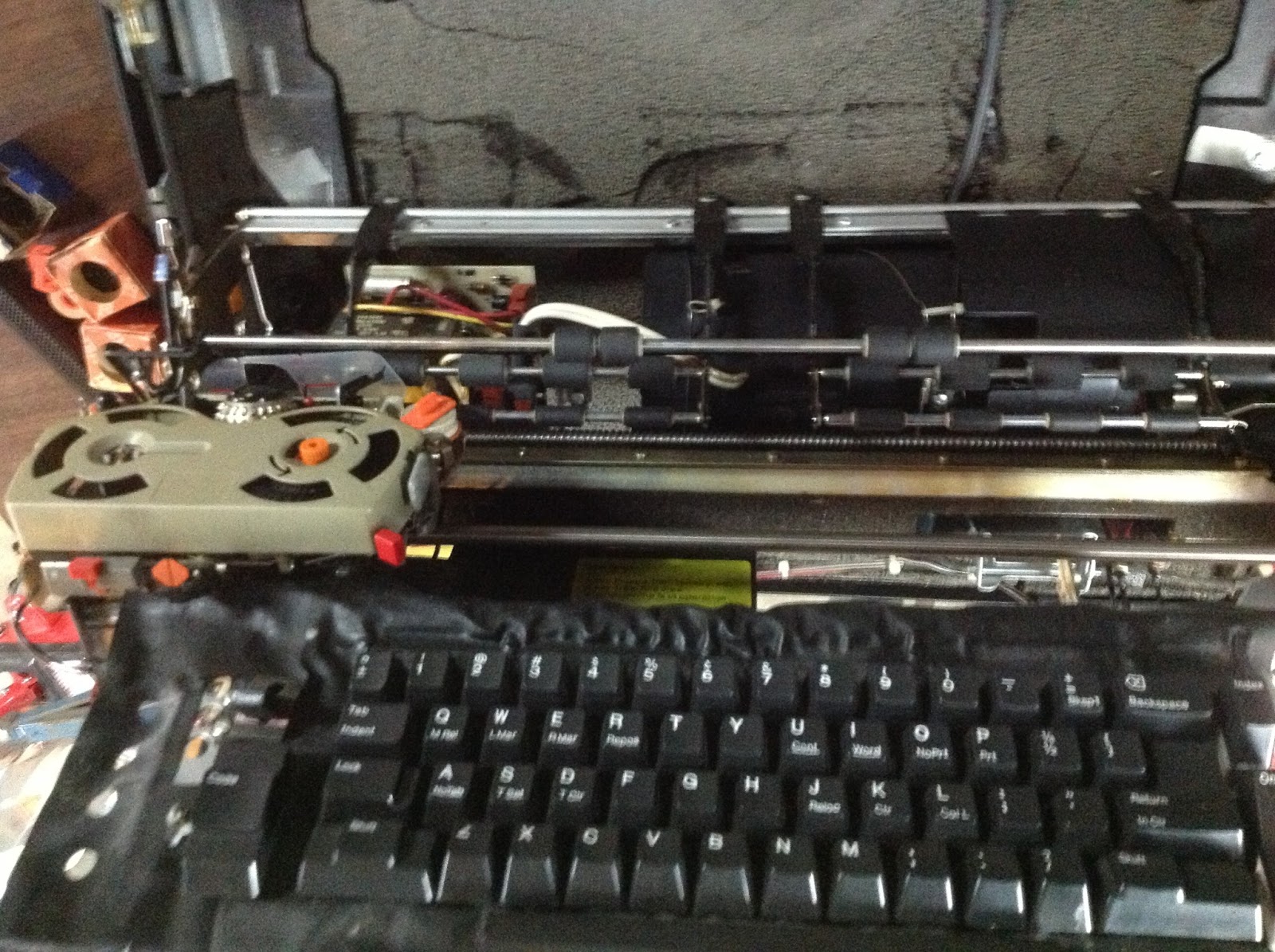 |
| Electronic 50 has keys separated from print mechanism |
 |
| Seolenoids and circuit board in Electronic 50 Selectric |
However, two issues remain that must be overcome. First, the typeball used on the E50 is incompatible with the Selectric 2, featuring more character positions to cite one difference. Thus a typeball from an 1130 won't work properly. As I hoped to find an APL typeball and run 1130 APL on my replica, this will be a barrier. Second, the microswitches and means of reporting the rotary position during operation of cycles, such as a basic print cycle, are different. Optical pulses are sampled by the circuit board in the E50, rather than microswitch contacts being activated. My interfacing my require some custom microswitches or an adapter circuit to convert to the kind of feedback signal expected by the 1130 console printer adapter logic, which believes it is connected to a 1053, not an E50. I may need to produce one or more custom typeballs or translate tilt/rotate codes on the fly in order to produce the intended printed characters from the E50 typeball.
The IBM solenoids operate at 48V, requiring me to design and build a circuit card taking 3.3V logic inputs and activating the solenoids with 48V at sufficient current to work properly. That is still in design, but I will build a prototype board shortly to begin testing the integration of the E50 into the 1130 system.
Testing the prototype of the console hw - part 1
The display light panels were formed using LEDs in the final pattern that will be illuminated behind a plexiglas panel in the pedestal unit that sits above the console printer on the IBM 1130. These were cabled to the display drivers, fanout logic, concentrators, switch debouncers and data links, which were attached to the FPGA 1130 and tested. Switches from scrap panels of IBM 3420 are used, along with toggle switches for the Console Entry Switch group temporarily mounted on a cardboard rectangle, and a rotary switch to be used for the Mode switch on the pedestal were wired in to test actual hardware components intended for the replica 1130.
The keyboard and console printer elements are not yet ready for testing, although temporary logic is provided to allow a PS/2 keyboard to be used for entry. The key layout is matched, but the keycap markings, shapes and colors are not the same as the 1130 and the feel is completely different. It will allow debugging and use of the system until the final keyboard mechanism is constructed. Similarly, emulation is provided for the IBM 1053 device used as the console printer, emitting ascii over the fpgalink to a PC which will display what is being 'typed' by the console device. These two emulated portions will be tested a bit later, followed by prototype testing of the final designs once my keyboard and printer hardware is ready.
 |
| Prototype of light panel being constructed |
 |
| 1130 Pedestal Light Panel |
The buttons and lights near the keyboard will be similar to these, although mined from scrap 3420 tape drive and scrap buttons found on ebay. These are wired through the debouncer to the concentrator.
 |
| 1130 Buttons and Lamps near the keyboard |
 |
| Scrap 3420 panel to provide buttons and lamps |
The keyboard itself is repurposed from the 029 Keypunch, and that would be the first choice if I can get my hands on a keypunch or the parts, otherwise I will need to come as close as possible.
 |
| Keyboard of the 1130 (or 029) |
The Console Entry Switches go through their own concentrator board, one I received from Richard Stofer, wired to some toggle switches bought on ebay. These are not an exact substitute for the 1130 switches but are very long toggle handles to permit mounting in a realistic setting in front of the console printer.
 |
| 1130 Console Entry Switches |
 |
| My CES prototype with R. Stofer's board |
Once the switches are mounted in their more permanent location on the console printer faceplate, this will be fully usable.
The test setup with the console display lights hooked into the 1130 - not working properly initially, recoding along with testing to fine tune. Didn't put enough capacitors protecting the + power to the board, to avoid the impacts of all the current switching into and out of the LED array. This removed glitches to yield a much more reliable transfer to the MAX7219 chips. Found a few bad LEDs, some broken wires in the harness and a few unsoldered leads on my prototype board. Cleaned up and moved on to debugging the displayed state of the lights. There are still glitches occuring, thus more work needed on the prototype board, as well as some wiring issues remaining in the right hand board. Progress is steady, however, and it is only a matter of time before this is solid enough to consider the design final. At that point I will design a production printed circuit board and build it.
 |
| Testing the light display panel hardware |
The button and switch entry unit were debugged, then tested with the 3420 tape unit buttons hooked through the debouncer board to the multiplexor board, whose link worked well with the console link function inside the fpga. Work is now underway to design a final printed circuit board for the button/switch entry logic, merging the debouncer and multiplexor boards into one. This will be fabbed by an outside service and then components soldered on after I receive the board.
When the production version circuit boards are built, I will conduct a second round of testing/debugging of the completed system.
When the production version circuit boards are built, I will conduct a second round of testing/debugging of the completed system.
The Search For Authentic Hardware
With realism of the experience for a person using the 1130 replica as a key objective, it was important to recreate as much of the system as reasonable. That is one of the reasons to build a physical panel with the blinking lights at full size, as well as the rationale for using a Selectric typewriter mechanism for the console output. This entry describes the process of acquiring and/or building the appropriate parts of the machine.
Scrap parts for some mainframe systems are still plentiful in the used markets. IBM tape drive units are particularly active on Ebay at this time, where the operator panels include the same kind of switches and lights as are used on the 1130 - plastic rectangles in red, green, and blue for the pushbutton switches and rectangular plastic blocks in white, yellow, red and green for the lights. Some of the buttons are usable as purchased, for example the "Start" and "Reset" buttons, but others will need the wording altered to match the 1130.
On the console pedestal, alongside the blinking lights, are a rotary mode switch on the right and a red emergency pull switch on the left side. I found a suitable rotary electrical switch to actuate the mode switch, allowing selection of 'single step', 'single storage cycle', 'single instruction', 'normal', 'interrupt run', 'load' and 'display' modes. I am using a scrap part knob from a different IBM mainframe to make the mode switch appear as accurate as possible. The emergency pull switch is a problem, even though it will not be operational, because it is so iconic for IBM mainframes. These are apparently highly prized souvenirs and extremely difficult to find. At this point, I expect I will be building a replica to install on this 1130.
I have described the challenges of converting a Selectric typewriter mechanism to server as the operator console, but a brief discussion of some additional factors is warranted. I used Craigslist to pick up a Selectric II, bought solenoids from an electronics supply house, and then bought an Electronic 50 as that is potentially easier to convert. However, the mechanism is housed differently, since there is no typewriter keyboard on the 1053 console printer. I will modify or build a housing that matches the 1130, place it around the converted typing mechanism, and integrate the tabs/carriage indicator. I will need to add a rocker for tab set/release, as well as button switches for Tab, Space and Return. Finally, the front of the printer also features 16 white tipped, silver handled toggle switches called the Console Entry Switches. I bought large toggle switches with extended handles, but will need to convert the ends with white caps to match. Most likely, I will grind down the ends to a stub cylinder, then glue on a white plastic cap that I make with a 3D printer.
The keyboard is a mechanical device with the unique heavy feel of the 029 Keypunch whose mechanism it leverages and the unique key layout and key shapes. I am currently trying to buy a very similar keyboard on Ebay, which is photoelectric not mechanical but otherwise identical in appearance and layout because it was built as part of a keypunch system. The initial price was just too high for the realism it provides ($350 plus shipping), especially because I can't feel the action of the keyboard in advance and don't know if I can implement the interlocking and need for a reset key to release a 'jammed' situation. I sent emails to the seller offering a lesser amount, but the buyer has not deigned to reply, although it was relisted a few times and reduced to (a still too high price of) $299. After the last auction elapsed, I emailed one final offer of $200, probably way too much but I am still receiving deafening silence from the seller. Sometimes people have firm ideas of what they believe their goods are worth, in spite of continued market evidence to the contrary, and they become offended by any suggestion of a lower price, not even bothering to counteroffer.
The fallback is to create a keyboard using mechanical switches, some foam or other material to increase the keystroke resistance, and some method yet unknown to create the lockout (jam) condition. Another alternative is to separate the keyboard portion of the electronic 50 typewriter, which is already fitted with microswitches, and make use of some form of that as a mechanical keyboard. This would certainly provide the interlock and need for a solenoid to release 'jams', but requires custom keycaps and may be difficult to map exactly to the 1130 keyboard layout. More research will be needed.
The tabletop will be wood with white laminate, similar to the actual 1130 table, but not full height off the floor. Instead, it will look as if someone had used a chain saw to cut off the top of an 1130, leaving just six inches or so below the lowest edge of the tabletop. The metal portions will be copied, as these are all painted and can be replicated pretty well - pebble finish except for the plate atop the keyboard which is smooth - and in authentic colors.
I have access to real 1130 systems at the nearby Computer History Museum and also at a nearby private collector's home, allowing me to measure more accurately, test coloring and finishes, and test out the keyboard action. The CHM machine can't be touched, although I might be able to arrange permission using gloves, but the collector's machine is going to be fully accessible. I would like to check out the intensity and behavior of the lights on the pedestal console display, and to record the noises of the 1130, but neither of these machines are powered. There are two powered machines I might get access to for the light investigation and recording - one nearby at a second private collector's home and the other near London in the UK at the National Museum of Computing.
I am producing peripheral replicas as possible - paper tape, plotter, card and printer devices are all possibilities. Initially the plotter is handled by a clever unit built by Richard Stofer that converts the plotter instuctions of the 1130 adapter into HP-GL commands over TCP/IP, allowing it to drive any HP-GL compatible plotter or printer. If I buy a plotter that could be forced into a replica housing, I might be able to produce the 1130-like plotter, but at worst it will be used to link to a HP-GL compatible laser printer.
I have bought a paper tape reader mechanism on Ebay (it was how I came to meet one of the private collectors in the area) which I will fit into a replica housing to look like the 1130 peripheral. I bought the punch block for a teletype - the dies and fitted holes that are driven to punch holes in paper tape - which I only need to fit to solenoids and install with a sprocketed driving mechanism in order to build the paper tape punch. If this pans out, I will also need to buy some blank paper tape stock on ebay.
Punched Card equipment is in short supply, but I may be able to create some form of punched card input/output. There are occasional readers or punches appearing on ebay - right now there is a duplicator (both reading and punching plus the card transport capability) but the offered price at $495 is a bit high since there is no guarantee it is in working condition. I have a mechanical keypunch (Wright 2600) and a box of 2000 blank cards, both bought on ebay, thus I could move forward on the reader/punch if I choose.
Line printers are difficult to build as a replica, mostly due to the lack of continuous form paper supplies. and the fact that chain or wheel based printers have long been replaced by other mechanisms like laser printers, but the right basic mechanism might show up somewhere and trigger a subproject.
Disk IO on the 1130 uses the 2310 mechanism and the 2316 disk cartridge. Used cartridges are found on ebay periodically, but not the drive mechanism. However, several other makers built similar products, including DEC (RK-05 disk), Pertec, and CDC, any one of which could be pressed into service. The unique 'grunting' sound of the actuator might need to be reproduced, since the mechanisms for seeking and positioning are different on the compatible drives, but many options exist. First, I could put flash memory inside a disk cartridge along with zigbee or similar wireless, allowing the cartridge to be placed into a mock disk mechanism and accessed - playing some simulated disk sounds as it operates. I have bought an IBM 8" floppy drive mechanism as it seems to use a mechanism most directly derived from the 1130's disk, thus it might provide the right grunting sound. I could use a floppy itself as the disk cartridge, or just use that part of the mechanism for authentic sounds - more investigation and design work is needed.
Other peripherals such as the 2250 graphic workstation, optical mark reader and alternative readers and printers, are not in scope at this time.
Scrap parts for some mainframe systems are still plentiful in the used markets. IBM tape drive units are particularly active on Ebay at this time, where the operator panels include the same kind of switches and lights as are used on the 1130 - plastic rectangles in red, green, and blue for the pushbutton switches and rectangular plastic blocks in white, yellow, red and green for the lights. Some of the buttons are usable as purchased, for example the "Start" and "Reset" buttons, but others will need the wording altered to match the 1130.
On the console pedestal, alongside the blinking lights, are a rotary mode switch on the right and a red emergency pull switch on the left side. I found a suitable rotary electrical switch to actuate the mode switch, allowing selection of 'single step', 'single storage cycle', 'single instruction', 'normal', 'interrupt run', 'load' and 'display' modes. I am using a scrap part knob from a different IBM mainframe to make the mode switch appear as accurate as possible. The emergency pull switch is a problem, even though it will not be operational, because it is so iconic for IBM mainframes. These are apparently highly prized souvenirs and extremely difficult to find. At this point, I expect I will be building a replica to install on this 1130.
I have described the challenges of converting a Selectric typewriter mechanism to server as the operator console, but a brief discussion of some additional factors is warranted. I used Craigslist to pick up a Selectric II, bought solenoids from an electronics supply house, and then bought an Electronic 50 as that is potentially easier to convert. However, the mechanism is housed differently, since there is no typewriter keyboard on the 1053 console printer. I will modify or build a housing that matches the 1130, place it around the converted typing mechanism, and integrate the tabs/carriage indicator. I will need to add a rocker for tab set/release, as well as button switches for Tab, Space and Return. Finally, the front of the printer also features 16 white tipped, silver handled toggle switches called the Console Entry Switches. I bought large toggle switches with extended handles, but will need to convert the ends with white caps to match. Most likely, I will grind down the ends to a stub cylinder, then glue on a white plastic cap that I make with a 3D printer.
The keyboard is a mechanical device with the unique heavy feel of the 029 Keypunch whose mechanism it leverages and the unique key layout and key shapes. I am currently trying to buy a very similar keyboard on Ebay, which is photoelectric not mechanical but otherwise identical in appearance and layout because it was built as part of a keypunch system. The initial price was just too high for the realism it provides ($350 plus shipping), especially because I can't feel the action of the keyboard in advance and don't know if I can implement the interlocking and need for a reset key to release a 'jammed' situation. I sent emails to the seller offering a lesser amount, but the buyer has not deigned to reply, although it was relisted a few times and reduced to (a still too high price of) $299. After the last auction elapsed, I emailed one final offer of $200, probably way too much but I am still receiving deafening silence from the seller. Sometimes people have firm ideas of what they believe their goods are worth, in spite of continued market evidence to the contrary, and they become offended by any suggestion of a lower price, not even bothering to counteroffer.
The fallback is to create a keyboard using mechanical switches, some foam or other material to increase the keystroke resistance, and some method yet unknown to create the lockout (jam) condition. Another alternative is to separate the keyboard portion of the electronic 50 typewriter, which is already fitted with microswitches, and make use of some form of that as a mechanical keyboard. This would certainly provide the interlock and need for a solenoid to release 'jams', but requires custom keycaps and may be difficult to map exactly to the 1130 keyboard layout. More research will be needed.
The tabletop will be wood with white laminate, similar to the actual 1130 table, but not full height off the floor. Instead, it will look as if someone had used a chain saw to cut off the top of an 1130, leaving just six inches or so below the lowest edge of the tabletop. The metal portions will be copied, as these are all painted and can be replicated pretty well - pebble finish except for the plate atop the keyboard which is smooth - and in authentic colors.
I have access to real 1130 systems at the nearby Computer History Museum and also at a nearby private collector's home, allowing me to measure more accurately, test coloring and finishes, and test out the keyboard action. The CHM machine can't be touched, although I might be able to arrange permission using gloves, but the collector's machine is going to be fully accessible. I would like to check out the intensity and behavior of the lights on the pedestal console display, and to record the noises of the 1130, but neither of these machines are powered. There are two powered machines I might get access to for the light investigation and recording - one nearby at a second private collector's home and the other near London in the UK at the National Museum of Computing.
I am producing peripheral replicas as possible - paper tape, plotter, card and printer devices are all possibilities. Initially the plotter is handled by a clever unit built by Richard Stofer that converts the plotter instuctions of the 1130 adapter into HP-GL commands over TCP/IP, allowing it to drive any HP-GL compatible plotter or printer. If I buy a plotter that could be forced into a replica housing, I might be able to produce the 1130-like plotter, but at worst it will be used to link to a HP-GL compatible laser printer.
I have bought a paper tape reader mechanism on Ebay (it was how I came to meet one of the private collectors in the area) which I will fit into a replica housing to look like the 1130 peripheral. I bought the punch block for a teletype - the dies and fitted holes that are driven to punch holes in paper tape - which I only need to fit to solenoids and install with a sprocketed driving mechanism in order to build the paper tape punch. If this pans out, I will also need to buy some blank paper tape stock on ebay.
Punched Card equipment is in short supply, but I may be able to create some form of punched card input/output. There are occasional readers or punches appearing on ebay - right now there is a duplicator (both reading and punching plus the card transport capability) but the offered price at $495 is a bit high since there is no guarantee it is in working condition. I have a mechanical keypunch (Wright 2600) and a box of 2000 blank cards, both bought on ebay, thus I could move forward on the reader/punch if I choose.
Line printers are difficult to build as a replica, mostly due to the lack of continuous form paper supplies. and the fact that chain or wheel based printers have long been replaced by other mechanisms like laser printers, but the right basic mechanism might show up somewhere and trigger a subproject.
Disk IO on the 1130 uses the 2310 mechanism and the 2316 disk cartridge. Used cartridges are found on ebay periodically, but not the drive mechanism. However, several other makers built similar products, including DEC (RK-05 disk), Pertec, and CDC, any one of which could be pressed into service. The unique 'grunting' sound of the actuator might need to be reproduced, since the mechanisms for seeking and positioning are different on the compatible drives, but many options exist. First, I could put flash memory inside a disk cartridge along with zigbee or similar wireless, allowing the cartridge to be placed into a mock disk mechanism and accessed - playing some simulated disk sounds as it operates. I have bought an IBM 8" floppy drive mechanism as it seems to use a mechanism most directly derived from the 1130's disk, thus it might provide the right grunting sound. I could use a floppy itself as the disk cartridge, or just use that part of the mechanism for authentic sounds - more investigation and design work is needed.
Other peripherals such as the 2250 graphic workstation, optical mark reader and alternative readers and printers, are not in scope at this time.
Learning experiences and new tools
This project is difficult and far-reaching precisely so it will drive me to learn a great deal about a wide range of subjects and skills. As such, it involves the need to confront some entirely new protocol, type of device, tool or aspect of design. Forward progress slows to a snails pace, frustration can surge, but eventually each area snaps into some mental focus, confidence grows and correctly operating mechanisms are the evidence of my success.
Linking the FPGA to other devices, both those built onto the Nexys2 board and the many external ones I am using, generally requires studying some protocol and set of electrical requirements, production of both soft hardware (VHDL) and physical boards, and extensive testing. There are many link protocols that can be used and I have deliberately spread my work across different ones to impel me to learn each. Serial communications, USB high speed stream mode, SPI, I2C and a 2 wire protocol proprietary to the MAX7219 chips. In addition, I had to learn how to access the DRAM chips on the Nexys2, the flash chips, and of course all the interfacing protocols for the Selectric based console and other peripherals.
In order to ensure I know how to access the various chips, I made use of a neat tool called the Bus Pirate which lets me drive and investigate the devices until I really understand the protocol. ref - Bus Pirate site
The logic analyzer also lets me snapshot the activity on the lines and see glitches, timing errors and other anomalies.
For the PC side, where I will emulate certain peripherals like card readers and pass the card images down to the machine, I decided to build this with a graphical interface, since I have no background in Windows GUI, and code it in Python, as I don't know that language but it appears to be worth learning.
Linking the FPGA to other devices, both those built onto the Nexys2 board and the many external ones I am using, generally requires studying some protocol and set of electrical requirements, production of both soft hardware (VHDL) and physical boards, and extensive testing. There are many link protocols that can be used and I have deliberately spread my work across different ones to impel me to learn each. Serial communications, USB high speed stream mode, SPI, I2C and a 2 wire protocol proprietary to the MAX7219 chips. In addition, I had to learn how to access the DRAM chips on the Nexys2, the flash chips, and of course all the interfacing protocols for the Selectric based console and other peripherals.
In order to ensure I know how to access the various chips, I made use of a neat tool called the Bus Pirate which lets me drive and investigate the devices until I really understand the protocol. ref - Bus Pirate site
 |
| Bus Pirate board |
The logic analyzer also lets me snapshot the activity on the lines and see glitches, timing errors and other anomalies.
For the PC side, where I will emulate certain peripherals like card readers and pass the card images down to the machine, I decided to build this with a graphical interface, since I have no background in Windows GUI, and code it in Python, as I don't know that language but it appears to be worth learning.
Researching the Electronic 50 prior to adapting it
The IBM Electronic 50 is not the same mechanism as the IBM 1053 (or 2741 terminal) from the 360 era, although roughly speaking it attacks the problem the same way. It uses solenoids and microswitches for feedback, just as does the 1053, but it was redesigned more fundamentally for electronic printing.
The keyboard and the printing mechanism are separated in the E50, with the keyboard activating reed switches that are read by the logic board, not by pulling on links that select the typeball position and unclutch the print mechanism. The print mechanism is driven by the logic board, thus many actions like carriage return are done entirely differently. Shifting between upper case and lower case is done separately at the keyboard (to record in the memory whether the entered keystroke is upper case or not) and in the print mechanism (cause the typeball to rotate 180 degrees to the upper or lower case position, since printing is at a different time from entry of the text.
The most important difference for my implementation is that the position of the carriage across a line is tracked electronically, as are the tab settings. The carriage is moved right or left (called escapement) by a spiral grooved rotating rod and a photocell is used to count holes corresponding to 50ths of an inch of movement. Even when a single character is typed, the machine just rotates the escapement rod while counting holes until the carriage has moved 5 holes (for 10 character per inch pitch) or 6 holes (for 12 cpi).
Backspace is the same mechanism, but selecting 'reverse' gear and subtracting holes from the counter that tracks current carriage position. Tab is implemented by the escapement rod turning and holes being counted until the current position reaches the next 'tab' position in internal memory of the logic board. Carriage return is reverse gear, same escapement mechanism, subtracting holes until the left margin (effectively the zero position of the carriage) is reached.
The escapement rod runs at two speeds - low and high - both of which can be forward or reverse direction. Thus, carriage return or tab go into high speed mode as long as the carriage is more than 1.5" from its destination position, then drop to low speed for the final distance.
The E50 uses a 96 character ball, unlike the Selectric II type ball used in the 1130, thus is typeball incompatible. The codes for printed characters are different, necessarily, because you can't address 96 characters with the same number of tilt and rotate positions as the Selectric I and Selectric II. Thus, my adapter will have to translate from the 1130 tilt/rotate codes and commands into the appropriate codes for the E50 mechanism.
While the 1053 printer mechanism did not provide feedback to the 1130 adapter about whether it was in upper or lower case, the E50 provides such a signal using a reed switch. The 1130 adapter tracks the position it last set for case, ensuring that it does not do an upshift when the mechanism is already in upper case position, since that will jam the physical mechanism. On the E50, the solenoid for changing shift is a toggle, change to upper if in lower or change to lower if in upper, plus it reports the actual case of the mechanism via signal. Much safer design.
On the other hand, the 1053 has a microswitch to trigger the 'end of line' signal whereas the E50 depends on the logic board to track the carriage position compared to the right margin setting, not on detecting the actual carriage position. The E50 has failure modes where the logical position tracked in the counter does not match the real position of the physical carriage, and the E50 has no way of detecting that. It could type off the right end, attempt to backspace or CR past the left margin, tab to the wrong spot, mis-space, or other errant behavior.
The E50 uses two voltage levels - TTL compatible 5V for logic signals and 12V used for solenoids. Reed switches are used throughout, pulling down the signal to 0 when closing and letting pullup resistors yank it back to 1 when the switch opens. Little magnets are affixed to various mechanisms that will activate these reed switches as necessary.
The core switch in the E50 is the Print Feedback Switch. Printer actions are driven by activating the print clutch (PSCC) which rotates a rod 360 degrees, that rod powers all the tilting, hammering onto paper and other movements of the mechanism. At 85 degrees of rotation, it closes and it reopens at 300 degrees. It is used to block attempts to print another character or take an action like backspace while the mechanism is still in motion and could cause a jam. Various actions are performed at the 85 and 300 point, such as releasing the PSCC at 85 once movement has begun or turning on the escapement solenoids (plus low speed or hi speed) at 85.
The E50 supports variable velocity for the typeball striking the paper, producing more even levels of darkness by adjusting strike velocity to the character being typed. This is a fixed correspondence to the character code, which I will handle at the same time that I translate from Selectric II to E50 tilt/rotate codes.
The cables onto the logic board are well marked, thus I have already identified the wires to use to activate the PSCC (print mechanism), escapement low/high speeds, escapement reverse, index, toggle shift case, toggle ribbon color, escapement operation, photocell lamp turnon, and correction (erase character) solenoids. I also know how to read the photocell output, shift state of the carriage, print feedback switch state, and even the switch (I won't use for the 1130) that changes between 10, 12 and proportional character per inch spacing. There is a solenoid to ring the bell which I will make use of, if there is a way for 1130 programs to activate this.
The 1053 printer has separate solenoids to upshift, downshift, go to red ribbon and go to black ribbon, while the E50 simply toggles shift and toggles ribbon color, so a bit of translation and state tracking will occur. The 1130 expects two signals, CB Response and Twr Interlock, generated to let the adapter know when it is safe to request the next character or operation. CB response will be generated by the print feedback switch, while Twr Interlock will be generated any time that Escapement is on (we are still moving toward some target carriage position).
I am building a driver board that will take 3.3V logic signals and emit the 12V to activate each solenoid, plus it will level shift the reed switch TTL values down to the 3.3V logic levels of the FPGA board. Once this is complete, I can begin debugging the FGPA code that connects the E50 mechanism to the 1130 adapter.
The keyboard mechanism looks like it is adaptable for use as the keyboard of the 1130! That is, it has interposers that lock it when one key is pressed so that a second key can't be simultaneously activated. A clutch causes a cam to rotate once when a key is pressed, the cam will reset the depressed key after its value is read. The key pressed activates various reed microswitches that yield a 7 bit keycode - the E50 tilt, rotate, rack and shift bits - and these are read by the logic after it waits 5 ms from the first activation to ensure all of them have reached their stable final state. I need to look more closely at how the clutch mechanism works with the keyboard, as it may be possible to replace the clutch linkages with solenoids thus totally isolating the keyboard from the rotating motor driven parts. This would suit my needs perfectly.
Unfortunately, during my investigations, I created a tear on one side of a delicate ribbon cable that connects the logic board to the print carriage, bringing the tilt, rotate, shift, ribbon and velocity signals to that carriage. I will need to repair or replace that cable before I can proceed, but there are no spare parts or spare machines that I can locate, thus some form of repair or substitution will be necessary. This cable flexes every time the carriage moves across a line, thus the replacement or repair work needs to accommodate that hostile environment.
The keyboard and the printing mechanism are separated in the E50, with the keyboard activating reed switches that are read by the logic board, not by pulling on links that select the typeball position and unclutch the print mechanism. The print mechanism is driven by the logic board, thus many actions like carriage return are done entirely differently. Shifting between upper case and lower case is done separately at the keyboard (to record in the memory whether the entered keystroke is upper case or not) and in the print mechanism (cause the typeball to rotate 180 degrees to the upper or lower case position, since printing is at a different time from entry of the text.
The most important difference for my implementation is that the position of the carriage across a line is tracked electronically, as are the tab settings. The carriage is moved right or left (called escapement) by a spiral grooved rotating rod and a photocell is used to count holes corresponding to 50ths of an inch of movement. Even when a single character is typed, the machine just rotates the escapement rod while counting holes until the carriage has moved 5 holes (for 10 character per inch pitch) or 6 holes (for 12 cpi).
Backspace is the same mechanism, but selecting 'reverse' gear and subtracting holes from the counter that tracks current carriage position. Tab is implemented by the escapement rod turning and holes being counted until the current position reaches the next 'tab' position in internal memory of the logic board. Carriage return is reverse gear, same escapement mechanism, subtracting holes until the left margin (effectively the zero position of the carriage) is reached.
The escapement rod runs at two speeds - low and high - both of which can be forward or reverse direction. Thus, carriage return or tab go into high speed mode as long as the carriage is more than 1.5" from its destination position, then drop to low speed for the final distance.
The E50 uses a 96 character ball, unlike the Selectric II type ball used in the 1130, thus is typeball incompatible. The codes for printed characters are different, necessarily, because you can't address 96 characters with the same number of tilt and rotate positions as the Selectric I and Selectric II. Thus, my adapter will have to translate from the 1130 tilt/rotate codes and commands into the appropriate codes for the E50 mechanism.
While the 1053 printer mechanism did not provide feedback to the 1130 adapter about whether it was in upper or lower case, the E50 provides such a signal using a reed switch. The 1130 adapter tracks the position it last set for case, ensuring that it does not do an upshift when the mechanism is already in upper case position, since that will jam the physical mechanism. On the E50, the solenoid for changing shift is a toggle, change to upper if in lower or change to lower if in upper, plus it reports the actual case of the mechanism via signal. Much safer design.
On the other hand, the 1053 has a microswitch to trigger the 'end of line' signal whereas the E50 depends on the logic board to track the carriage position compared to the right margin setting, not on detecting the actual carriage position. The E50 has failure modes where the logical position tracked in the counter does not match the real position of the physical carriage, and the E50 has no way of detecting that. It could type off the right end, attempt to backspace or CR past the left margin, tab to the wrong spot, mis-space, or other errant behavior.
The E50 uses two voltage levels - TTL compatible 5V for logic signals and 12V used for solenoids. Reed switches are used throughout, pulling down the signal to 0 when closing and letting pullup resistors yank it back to 1 when the switch opens. Little magnets are affixed to various mechanisms that will activate these reed switches as necessary.
The core switch in the E50 is the Print Feedback Switch. Printer actions are driven by activating the print clutch (PSCC) which rotates a rod 360 degrees, that rod powers all the tilting, hammering onto paper and other movements of the mechanism. At 85 degrees of rotation, it closes and it reopens at 300 degrees. It is used to block attempts to print another character or take an action like backspace while the mechanism is still in motion and could cause a jam. Various actions are performed at the 85 and 300 point, such as releasing the PSCC at 85 once movement has begun or turning on the escapement solenoids (plus low speed or hi speed) at 85.
The E50 supports variable velocity for the typeball striking the paper, producing more even levels of darkness by adjusting strike velocity to the character being typed. This is a fixed correspondence to the character code, which I will handle at the same time that I translate from Selectric II to E50 tilt/rotate codes.
The cables onto the logic board are well marked, thus I have already identified the wires to use to activate the PSCC (print mechanism), escapement low/high speeds, escapement reverse, index, toggle shift case, toggle ribbon color, escapement operation, photocell lamp turnon, and correction (erase character) solenoids. I also know how to read the photocell output, shift state of the carriage, print feedback switch state, and even the switch (I won't use for the 1130) that changes between 10, 12 and proportional character per inch spacing. There is a solenoid to ring the bell which I will make use of, if there is a way for 1130 programs to activate this.
The 1053 printer has separate solenoids to upshift, downshift, go to red ribbon and go to black ribbon, while the E50 simply toggles shift and toggles ribbon color, so a bit of translation and state tracking will occur. The 1130 expects two signals, CB Response and Twr Interlock, generated to let the adapter know when it is safe to request the next character or operation. CB response will be generated by the print feedback switch, while Twr Interlock will be generated any time that Escapement is on (we are still moving toward some target carriage position).
I am building a driver board that will take 3.3V logic signals and emit the 12V to activate each solenoid, plus it will level shift the reed switch TTL values down to the 3.3V logic levels of the FPGA board. Once this is complete, I can begin debugging the FGPA code that connects the E50 mechanism to the 1130 adapter.
The keyboard mechanism looks like it is adaptable for use as the keyboard of the 1130! That is, it has interposers that lock it when one key is pressed so that a second key can't be simultaneously activated. A clutch causes a cam to rotate once when a key is pressed, the cam will reset the depressed key after its value is read. The key pressed activates various reed microswitches that yield a 7 bit keycode - the E50 tilt, rotate, rack and shift bits - and these are read by the logic after it waits 5 ms from the first activation to ensure all of them have reached their stable final state. I need to look more closely at how the clutch mechanism works with the keyboard, as it may be possible to replace the clutch linkages with solenoids thus totally isolating the keyboard from the rotating motor driven parts. This would suit my needs perfectly.
Unfortunately, during my investigations, I created a tear on one side of a delicate ribbon cable that connects the logic board to the print carriage, bringing the tilt, rotate, shift, ribbon and velocity signals to that carriage. I will need to repair or replace that cable before I can proceed, but there are no spare parts or spare machines that I can locate, thus some form of repair or substitution will be necessary. This cable flexes every time the carriage moves across a line, thus the replacement or repair work needs to accommodate that hostile environment.
Designing the E50 interface to the 1130
First step was to work out how to use the power supply to drive the 12V for the solenoids, which was a question mark because the power supply board had an IBM MST logic module, multiple mysteriously marked regulators and other circuitry on it, which might have required a specific handshake before delivering full power. Fortunately, I discovered that a simple bridge across two wires was enough to convince the PS to deliver full 5V and 12V power. I intend to use the 5V for the LEDs and other circuit boards that run at TTL levels, as well as the reed switch, photocell and photocell lamp inside the E50.
Having measured the resistance of the solenoid coils, I know what currents and power levels they will require and based on that, designed the driver circuit. The input is 3.3V logic levels from the FPGA, which will drive the solenoids from the 12V supply. I will prototype one of the driver circuits, verify operation and then have a board built for surface mount transistors and resistors to fit compactly into the printer enclosure.
Meanwhile, I used a lab power supply to validate the operation of the solenoids for the basic motor circuit. It was erratic turning on when the power switch was activated, caused by lubricating oil that got into the motor switch and partially burned a contact due to arcing. It was unreliable even after cleaning so I replaced it with a switch from the Selectric II typewriter I originally bought.
At this moment, the carriage is jammed at the left margin and the escapement lead screw is not turning, manually or under motor power. This also needs some investigation but the basic mechanism is clearly suitable for use as the 1130's console printer.
It was my belief that the signal listed as PUC was a switch reporting the shift status, but it is all a bit confusing, since the connector to the carriage where that signal is included does not +5V, the voltage level used with reed switches. The cable only carries ground, +12V and some control lines. My working hypothesis is that the machine does not discrete upshift and downshift solenoids, but further investigation is necessary before moving ahead on the design. The extended theory of operation manual for the E50 explicitly mentions a shift mode switch used for reporting the position of the mechanism. The diagram shows it swinging between 0V and 5V, but indicates the status at the halfway point of the PSCC rotation. Not sure if the switch maintains its 'value' when the shift movement is complete. Commanding the carrier to shift appears to require only the R2 solenoid and PSCC activation. I need to see if downshift is the same code or a different one.
Further web research suggests that the ribbon cartridge on the later Selectrics (and the Electronic xx models) did not support multiple colors, so that the shift to red and shift to black cannot be implemented. I will have those commands seem to work correctly, signalling completion at an appropriate time, to preserve programming compatibility.
I am still unable to identify the purpose of the RSH solenoid in the carriage assembly. It appears I will need to fire the solenoids to see if I can identify what each does. The tear in the ribbon cable affects only the velocity and correction solenoids. This is underway now.
A bit more testing has to be done and I must repair the ribbon cable, then I can begin testing candidate logic for my interface module.
My module has to support the tab set, tab clr, space, return and tab buttons on the console printer, as well as offering a way to set left and right margins. I am also working on the assumption that the printer operates in 10 character per inch mode, thus the scale across the front suggests a 13" wide printable line with one division of the scale covering a single character on the paper at 10 CPI.
The Electronic Model 50 is a wide platen machine, 19", which will cause difficulties fitting it inside an 1130 sized printer cover. I am not sure what I will do to address this particular issue; might have to tolerate some distortion from scale.
Having measured the resistance of the solenoid coils, I know what currents and power levels they will require and based on that, designed the driver circuit. The input is 3.3V logic levels from the FPGA, which will drive the solenoids from the 12V supply. I will prototype one of the driver circuits, verify operation and then have a board built for surface mount transistors and resistors to fit compactly into the printer enclosure.
Meanwhile, I used a lab power supply to validate the operation of the solenoids for the basic motor circuit. It was erratic turning on when the power switch was activated, caused by lubricating oil that got into the motor switch and partially burned a contact due to arcing. It was unreliable even after cleaning so I replaced it with a switch from the Selectric II typewriter I originally bought.
At this moment, the carriage is jammed at the left margin and the escapement lead screw is not turning, manually or under motor power. This also needs some investigation but the basic mechanism is clearly suitable for use as the 1130's console printer.
It was my belief that the signal listed as PUC was a switch reporting the shift status, but it is all a bit confusing, since the connector to the carriage where that signal is included does not +5V, the voltage level used with reed switches. The cable only carries ground, +12V and some control lines. My working hypothesis is that the machine does not discrete upshift and downshift solenoids, but further investigation is necessary before moving ahead on the design. The extended theory of operation manual for the E50 explicitly mentions a shift mode switch used for reporting the position of the mechanism. The diagram shows it swinging between 0V and 5V, but indicates the status at the halfway point of the PSCC rotation. Not sure if the switch maintains its 'value' when the shift movement is complete. Commanding the carrier to shift appears to require only the R2 solenoid and PSCC activation. I need to see if downshift is the same code or a different one.
Further web research suggests that the ribbon cartridge on the later Selectrics (and the Electronic xx models) did not support multiple colors, so that the shift to red and shift to black cannot be implemented. I will have those commands seem to work correctly, signalling completion at an appropriate time, to preserve programming compatibility.
I am still unable to identify the purpose of the RSH solenoid in the carriage assembly. It appears I will need to fire the solenoids to see if I can identify what each does. The tear in the ribbon cable affects only the velocity and correction solenoids. This is underway now.
A bit more testing has to be done and I must repair the ribbon cable, then I can begin testing candidate logic for my interface module.
My module has to support the tab set, tab clr, space, return and tab buttons on the console printer, as well as offering a way to set left and right margins. I am also working on the assumption that the printer operates in 10 character per inch mode, thus the scale across the front suggests a 13" wide printable line with one division of the scale covering a single character on the paper at 10 CPI.
The Electronic Model 50 is a wide platen machine, 19", which will cause difficulties fitting it inside an 1130 sized printer cover. I am not sure what I will do to address this particular issue; might have to tolerate some distortion from scale.
Testing console printer interface
The testing plan for the console printer has three phases. First, I will use a test rig to validate the signals, timing and behavior I expect from the Electronic 50 Typewriter mechanism I leveraged, second will involve testing with the logic instantiated in the fpga 1130 but using a prototype driver board, then finally I will test the final production build of the board and connections.
 |
| Arduino based test rig to explore interface approach |
Tuesday - My test rig was built with an Arduino microcontroller (Mega board) and the relay shield, giving me four relays to drive the 12V solenoid activations and a enough input pins to sense all the reed switch and photocell inputs from the E50. I put a pluggable breadboard between the Arduino rig and the E50, allowing me to change which tilt, rotate and other solenoids are selected by each relay, as well as changing other status signals from the typewriter mechanism.
 |
| Arduino microcontroller with relay shield to drive solenoids |
The tilt and rotate solenoids seem stiff - dried grease from age affects many of these older machines. I will clean and lubed the entire mechanism to ensure more reliable operation. I have successfully shifted case and fired the typeball for simple characters, plus operated the mechanism that moves the carriage left and right at low and high speed. Everything is looking quite good.
 |
| Driving the mechanism with my test rig |
 |
| Solenoids and grooved cam drum on underside of carriage |
 |
| Logic board of E50 - not used in this project |
I should receive the components for the driver board tomorrow, whence I can build a prototype single driver, verify the design and then fire off an order for a PCB to mount under the typewriter frame in place of the existing logic board. As an added bonus, the power supply from the E50 will give me all the clean 5V power I need to drive the LEDs in the console display panel and other places on the replica 1130.
The machine is quite messy, with excess oil in places it doesn't belong, sticky partially dried lubricant in places that should have fresh oil or grease, and the universal problem with the IBM typewriters of disintegrating foam inside. Soundproofing becomes a viscous tarry substance or shreds and floats into places it shouldn't be. I am going to clean it off with isopropyl alcohol then lubricate it properly - that should improve performance and reliability.
Wednesday - After about six hours of scraping off the soundproofing, then cleaning and relubricating the typewriter, I am ready to resume testing of my interface. I had to pick up the appropriate oil (Mobil 1 0W-20), grease (Mobile 1 synthetic) and cleaning supplies in order to finish the cleanup. I have my driver board parts, but they are very tiny surface mount parts (e.g. 0805 size resistors), which are harder to prototype without creating the board first. Will run tomorrow out to find some kind of prototyping board suitable for mounting the transistor, but use old school style full sized resistors for ease of construction. Should finish up the prototype and test Thursday, plus the design of the production board and send it off to be manufactured.
Friday - Prototype tested, works very well, thus on to PCB ordering. Having my set of challenges forcing the PCB design software to produce clean output - it keeps placing signal lines or vias (holes connecting signals on different layers of the board) on top of each other, touching components or overlapping the lettering/outlines of the silkscreen layer. Finally produced clean design files and shopping around for best combination of price and delivery time.
Sunday - finished and ordered the PCB boards to manage button and switch inputs and the LED outputs. It took lots of thought and hand routing to get the connections made among the fourteen chips and other parts. The automatic routing built into the PCB software was unable to converge on a solution, forcing me into manual mode. The other boards, for the LED panel and typewriter solenoid drivers, were easily handled by the automatic routing algorithm and needed just a few hours of tweaking to get into production ready state.
My boards are using surface mount components, which are difficult to solder by hand, so I have bought the parts to build my own solder reflow oven, where I can place all the parts into solder paste on the board at once, then heat it in the oven with the proper temperature ramp, causing the solder to melt, pull the parts into proper alignment and then cool to hardened high quality solder connections. I should have the oven completed by Tuesday evening. I am using a PID controller (proportional integral derivative) with a thermocouple, tied to a solid state relay to modulate the heat in an inexpensive toaster oven. It is essential to follow a specific heat profile, set by the maker of the solder paste being used, to produce good solder joints:
- first, the board temperature is raised slowly to almost the melting point of solder, typical target rates are 1-2 degrees C per second.
- next it is raised a bit and held steady to boil off the flux and clean the surfaces that will be bonded, long enough to eliminate any voids that may form around air bubbles or liquid flux. A representative soak phase is about a minute.
- the oven should then move the temperature up quickly to a safe margin above the melting point of the solder paste being used, which then flows over the bonding surfaces. Surface tension of the liquified solder will pull the solder away from the gaps between pads and will drag components into alignment with the pad to which they are being attached. The time to complete this step may also be one minute long.
- the board is then cooled at a moderate pace to minimize thermal shock, causing the solder to solidify. Once cool enough, it is removed and checked to ensure all joints are properly done, perhaps cooling at 2 C per second.
The solder is in a paste that is smeared on the pads, then each part is pushed into the paste where it sits waiting for the melting phase inside the oven. Because solder, flux and the components contain materials like lead that are unhealthy, the oven can never be used for food. I will mark it as contaminated by hazardous materials to avoid inadvertent misuse in the future.
After a bit of practice with the reflow oven, I will wait for my boards to come back from the manufacturers (Oshpark and Sunstone) then assemble them. All of the components to install on the boards are on their way from Digikey or already on hand.
 |
| E50 Power Supply - 12V for E50 and 5V for my other logic boards |
Wednesday - After about six hours of scraping off the soundproofing, then cleaning and relubricating the typewriter, I am ready to resume testing of my interface. I had to pick up the appropriate oil (Mobil 1 0W-20), grease (Mobile 1 synthetic) and cleaning supplies in order to finish the cleanup. I have my driver board parts, but they are very tiny surface mount parts (e.g. 0805 size resistors), which are harder to prototype without creating the board first. Will run tomorrow out to find some kind of prototyping board suitable for mounting the transistor, but use old school style full sized resistors for ease of construction. Should finish up the prototype and test Thursday, plus the design of the production board and send it off to be manufactured.
 |
| Circuit prototype for solenoid driver for E50 |
Friday - Prototype tested, works very well, thus on to PCB ordering. Having my set of challenges forcing the PCB design software to produce clean output - it keeps placing signal lines or vias (holes connecting signals on different layers of the board) on top of each other, touching components or overlapping the lettering/outlines of the silkscreen layer. Finally produced clean design files and shopping around for best combination of price and delivery time.
Sunday - finished and ordered the PCB boards to manage button and switch inputs and the LED outputs. It took lots of thought and hand routing to get the connections made among the fourteen chips and other parts. The automatic routing built into the PCB software was unable to converge on a solution, forcing me into manual mode. The other boards, for the LED panel and typewriter solenoid drivers, were easily handled by the automatic routing algorithm and needed just a few hours of tweaking to get into production ready state.
 |
| Bottom side of input control board PCB I designed |
 |
| Top side of the input control PCB I submitted to the fab |
- first, the board temperature is raised slowly to almost the melting point of solder, typical target rates are 1-2 degrees C per second.
- next it is raised a bit and held steady to boil off the flux and clean the surfaces that will be bonded, long enough to eliminate any voids that may form around air bubbles or liquid flux. A representative soak phase is about a minute.
- the oven should then move the temperature up quickly to a safe margin above the melting point of the solder paste being used, which then flows over the bonding surfaces. Surface tension of the liquified solder will pull the solder away from the gaps between pads and will drag components into alignment with the pad to which they are being attached. The time to complete this step may also be one minute long.
- the board is then cooled at a moderate pace to minimize thermal shock, causing the solder to solidify. Once cool enough, it is removed and checked to ensure all joints are properly done, perhaps cooling at 2 C per second.
The solder is in a paste that is smeared on the pads, then each part is pushed into the paste where it sits waiting for the melting phase inside the oven. Because solder, flux and the components contain materials like lead that are unhealthy, the oven can never be used for food. I will mark it as contaminated by hazardous materials to avoid inadvertent misuse in the future.
After a bit of practice with the reflow oven, I will wait for my boards to come back from the manufacturers (Oshpark and Sunstone) then assemble them. All of the components to install on the boards are on their way from Digikey or already on hand.
Great start on keyboard realism with ebay purchase
The keyboard used with the 1130 is the mechanical keyboard from the 029 keypunch, which has quite a different feel from the microswitch based keyboards of present day systems. The 1130 used the same shape and coloring as the 029 keys, with slightly differences in the number of keys and their assignment.
I came across a keyboard on Ebay that was from a data entry system that competed with the IBM 029 and 129 products, thus it was modeled closely on the look and feel of the IBM version. This is an excellent basis upon which to build my 1130 replica keyboard.
The keyboard does not use the mechanical bail switch decoding mechanism of the IBM versions, instead it uses photocells to detect keypresses. As you can see, the colors are slightly different, most obvious with the darker grey in my unit, but this is well within the bounds of human memory for absolute hues, meaning that it will be perceived to be the same as the 1130 version unless compared directly. This is especially true for most people who will have only a past memory of the actual keyboard.
I will need to do some investigation once it arrives to discover how to identify keypresses, then build my interface logic to translate this to 1130 keyboard behaviors. Fortunately, there is a patent for the mechanism that provides some insight into its construction and use. The interface looks super simple to create. Further, the mechanism seems to provide the latching, need to restore and other characteristics that I want my keyboard to exhibit, so as to be quite reminiscent of the IBM 1130 keyboard. I have included a diagram from the patent here to illustrate the suitability of this keyboard for my purpose.
.
 |
| IBM 1130 keyboard |
 |
| Keyboard from an IBM 029 Keypunch |
I came across a keyboard on Ebay that was from a data entry system that competed with the IBM 029 and 129 products, thus it was modeled closely on the look and feel of the IBM version. This is an excellent basis upon which to build my 1130 replica keyboard.
 |
| Ebay keyboard I acquired for use with 1130 project |
 |
| Another view of the keyboard from ebay |
I will need to do some investigation once it arrives to discover how to identify keypresses, then build my interface logic to translate this to 1130 keyboard behaviors. Fortunately, there is a patent for the mechanism that provides some insight into its construction and use. The interface looks super simple to create. Further, the mechanism seems to provide the latching, need to restore and other characteristics that I want my keyboard to exhibit, so as to be quite reminiscent of the IBM 1130 keyboard. I have included a diagram from the patent here to illustrate the suitability of this keyboard for my purpose.
 |
| Diagram from US patent 3,092,310 granted June 1963 |
Creating reflow oven to build printed circuit boards
Printed circuit boards have evolved from using components whose pins or wire leads fit through a hole in the board, to use of surface mount devices that do not require any hole. These permit boards to be composed of many layers practically, because the pins/wires of the devices are not interfering with any of the layers other than the top one that contains the component. This has been accompanied by the continual shrinking of the size of these components, all of which makes hand-soldering more and more difficult. Since the mainstream uses these surface mount devices (SMD), manufacturers of chips and other parts have shifted to SMD. It is impossible to get certain chips in a traditional, non-SMD packaging. Such is the case for a few chips that were ideal for use in my project.
Factory production of PCBs make use of reflow, where all the components are soldered to the board in a single pass. In one method, the devices placed on their intended copper connection pads with a sticky solder paste, then heated in an oven with a careful ramp up and cooldown process that minimizes thermal shock to the parts while producing excellent connections. The boards are placed in a reflow oven to heat and cool them. Commercial ovens are many thousands of dollars, but hobbyists have found ways to produce workable ovens for under $100 - I took on such a project to deal with the boards I am creating for the 1130 project.
I leveraged an old case I had in my garage, placing the circuitry for my oven into it. I bought an inexpensive 1500W toaster oven to use - the boards and solders contain lead and other elements that are not good to ingest - even being absorbed from the fingers at low rates. This will never be used to prepare food, because it is now contaminated by lead, bismuth and other metals.
I inserted a temperature probe (thermocouple) into the oven and removed the power plug from the end of the cable. In the old case to the left, I inserted a PID controller, SSR and the power cable from the toaster oven. I wired them up and put on a power cable with plug. The PID controller is a unit that will get the oven to a selected temperature and hold it there very accurately.
The name PID stands for proportional integral derivative - but the essence is that this is a smart controller that looks at feedback from the probe and figures out how to provide power to the oven to reach and hold the temperature.
The SSR is a solid state relay, a device that will switch the power to the toaster oven on and off as needed. In operation, the PID is usually pulsing or cycling the power to the oven, which you see by the light on the oven flashing on and off.
As the oven approaches the right temperature, the light flickers on for shorter and shorter periods. If it simply stayed on till hitting the temperature, the glowing heating elements in the over would keep adding heat as they cooled, pushing the temp inside the oven way over the target before the elements cooled all the way down. The controller autotunes itself, learning how to 'sneak up on' the right temp by lowering the heat of the elements at the right rate.
I put a thin layer of solder paste on the copper pads where devices should be soldered. The device plops into the paste and is held on the board by the stickiness of the gooey paste. The board goes in the oven and begins heating. When the paste gets hot enough, the goo part, which is called flux, melts and evaporates. This cleans off metal corrosion and dirt from the metal surfaces, ensuring that the solder can bond. The heat goes up gradually enough to make sure that the flux is fully evaporated before turning the metal part of the paste into flowing solder - otherwise air bubbles might cause poor solder joints.
The solder paste then reaches its liquification temperature and flows. Surface tension of the liquid solder causes it to form a bulging surface on the copper pads and device pins, while sucking away from the non metal part of the board. This puts the solder on each pin where it belongs and not bridging between the pins. As an added bonus, the power of the surface tension will pull the component into alignment, so that it does not need to be placed with extreme precision before soldering.
The designer of a PCB will usually have a 'stencil' made from the design of the top layer - generating a plastic sheet with openings where paste should be applied atop copper pads. This is placed atop the naked PCB, paste is then applied with a squeegee like tool (like a putty knife) to produce the right depth of paste on each pad. This adds $10 or more to each board designed, thus some will apply the paste without the guidance of a stencil.
I bought some junk circuit boards and surplus SMD chips at a local electronics shop to practice with, and have worked out the right amount of paste and timing for my oven. This was tricky to get right. Too much paste and a big ball of solder formed, which would bridge more than one pin if the SMD device had very small, closely packed pins. Too little and it didn't reliably form solder joints nor pull the device into alignment. Fortunately, the minimum amount is not that sensitive, even pretty thin swipes yielded satisfactory joints as long as the device was fairly well aligned.
Not using a stencil produces some waste goo placed on undesired spots of the PCB, which yields teeny dots of solder to flake off after using the oven. Since a 5cc syringe of solder paste is about $15, waste costs money as well as inconvenience. If solder bridges do form because of too much paste, they can be fixed by a process called 'reword' where you place a copper braid onto the blog while heating it, the copper braid will suck off the excess solder (wicking it up the same way that the wick of a candle will draw molten wax up to the tip of the wick where it burns). One tries to minimize the need for rework, as each application of heat shocks the parts and potentially could lead to some damage to teeny pins if I move them too much during fixes.
Another interesting problem concerns boards that are designed to mount parts on both the 'top' and 'bottom' faces of the PCB. If you solder one side, then flip the board over and solder the second face, the solder on the bottom is becoming molten again during the second pass in the oven. The parts might drop off or shift out of alignment. This is solved various ways in production, often by putting a tiny dot of epoxy glue under each component that will go on the 'bottom' face when the board is soldered a second time. The heat of the oven causes the epoxy to harden at the same time that the solder is molten, thus the part won't fall off even if the solder is melted the second time in the oven since the glue stays firm.
I have a different way to approach this, based on the availability of different solder pastes with different temperature profiles. My plan is to solder the 'bottom' face components using a paste with a higher melting point. When I flip the board to solder parts on the other side, I use a lower temperature paste. If the oven never gets hot enough to melt the solder on the bottom parts, then they will not fall off! Commonly available pastes have more than 200 degrees F difference in melting points, far more than the inaccuracies in my temperature control of the oven.
Now I am ready to solder the parts onto my 1130 printed circuit boards using the low temp paste, as soon as they arrive from the PCB manufacturer. With some practice learning how to use the normal (high) temperature paste, I can do the double sided component placement for my 'input controller' board since I put integrated circuits and other parts on both faces to simplify the wire routing.
My first PCB arrived today - it was a 2 day turnaround which skipped several steps that the others will include, such as the green colored 'solder mask' that insulates and protects all but the copper pads where parts are soldered, and it does not have the printed outlines and labels for parts (silkscreen layer). Functionally, it is fine for the purpose - it is a card that I will install inside the typewriter to interface it properly to my system. It has drivers that will activate the solenoids under control of the FPGA board.
I installed the parts (other than the connectors for the edge because they would make it hard for the PCB to sit evenly in the oven), using the solder paste, then put it into the reflow oven and presto - perfectly soldered board.
Unfortunately I had miscounted my parts and was short two resistors, so when I pick some up tomorrow I will hand solder the remaining two onto the board. The resistors are about the size of a flea, very easy to lose and challenging to pick up with the tweezers and put into place - think about how hard it will be to solder it on.
The connectors were placed once the board cooled down, and soldered in, after which I did a full test of the connections. Everything looks great!
After I bought some extra resistors, I hand soldered them and had a completed board. The resistors are the small rectangles you see to the side of the transistors which are the larger dark rectangles. They are normal size for surface mount resistors, a mere .08" long by .05" wide, but the parts can be as small as 1/100 of an inch long. Tweezers and a steady hand are necessary to work with them.
It was plugged into the typewriter and I am beginning to run some candidate logic sequences to verify that I am driving the operations correctly, such as carriage return, line feed, shift case, tab, and of course typing letters. So far, it is working exactly as I expected. Need to complete my fpga logic module then kick off detailed testing.
Sometime this weekend I will spray the board with a protectant seal, using a silcone conformal spray, similar to the solder masks on modern boards but also protecting the components on the board. That will keep it in good order when mounted underneath the typewriter mechanism, subject to vibration, heat and grease/oil drippings.
The board is mounted on the underside below the space where the carriage travels, in the place that the IBM logic board was mounted before I began the conversion. Besides the cables connecting the board to the typewriter mechanism (most are connected in the picture below), there are several cables that will link this to the FPGA 1130 board and power feeds on the side delivering clean 5V and 12V power for use by other logic boards.
Factory production of PCBs make use of reflow, where all the components are soldered to the board in a single pass. In one method, the devices placed on their intended copper connection pads with a sticky solder paste, then heated in an oven with a careful ramp up and cooldown process that minimizes thermal shock to the parts while producing excellent connections. The boards are placed in a reflow oven to heat and cool them. Commercial ovens are many thousands of dollars, but hobbyists have found ways to produce workable ovens for under $100 - I took on such a project to deal with the boards I am creating for the 1130 project.
I leveraged an old case I had in my garage, placing the circuitry for my oven into it. I bought an inexpensive 1500W toaster oven to use - the boards and solders contain lead and other elements that are not good to ingest - even being absorbed from the fingers at low rates. This will never be used to prepare food, because it is now contaminated by lead, bismuth and other metals.
 |
| My reflow oven and controller |
The name PID stands for proportional integral derivative - but the essence is that this is a smart controller that looks at feedback from the probe and figures out how to provide power to the oven to reach and hold the temperature.
 |
| PID controller to hold the oven at a target temperature |
The SSR is a solid state relay, a device that will switch the power to the toaster oven on and off as needed. In operation, the PID is usually pulsing or cycling the power to the oven, which you see by the light on the oven flashing on and off.
As the oven approaches the right temperature, the light flickers on for shorter and shorter periods. If it simply stayed on till hitting the temperature, the glowing heating elements in the over would keep adding heat as they cooled, pushing the temp inside the oven way over the target before the elements cooled all the way down. The controller autotunes itself, learning how to 'sneak up on' the right temp by lowering the heat of the elements at the right rate.
I put a thin layer of solder paste on the copper pads where devices should be soldered. The device plops into the paste and is held on the board by the stickiness of the gooey paste. The board goes in the oven and begins heating. When the paste gets hot enough, the goo part, which is called flux, melts and evaporates. This cleans off metal corrosion and dirt from the metal surfaces, ensuring that the solder can bond. The heat goes up gradually enough to make sure that the flux is fully evaporated before turning the metal part of the paste into flowing solder - otherwise air bubbles might cause poor solder joints.
The solder paste then reaches its liquification temperature and flows. Surface tension of the liquid solder causes it to form a bulging surface on the copper pads and device pins, while sucking away from the non metal part of the board. This puts the solder on each pin where it belongs and not bridging between the pins. As an added bonus, the power of the surface tension will pull the component into alignment, so that it does not need to be placed with extreme precision before soldering.
The designer of a PCB will usually have a 'stencil' made from the design of the top layer - generating a plastic sheet with openings where paste should be applied atop copper pads. This is placed atop the naked PCB, paste is then applied with a squeegee like tool (like a putty knife) to produce the right depth of paste on each pad. This adds $10 or more to each board designed, thus some will apply the paste without the guidance of a stencil.
I bought some junk circuit boards and surplus SMD chips at a local electronics shop to practice with, and have worked out the right amount of paste and timing for my oven. This was tricky to get right. Too much paste and a big ball of solder formed, which would bridge more than one pin if the SMD device had very small, closely packed pins. Too little and it didn't reliably form solder joints nor pull the device into alignment. Fortunately, the minimum amount is not that sensitive, even pretty thin swipes yielded satisfactory joints as long as the device was fairly well aligned.
Not using a stencil produces some waste goo placed on undesired spots of the PCB, which yields teeny dots of solder to flake off after using the oven. Since a 5cc syringe of solder paste is about $15, waste costs money as well as inconvenience. If solder bridges do form because of too much paste, they can be fixed by a process called 'reword' where you place a copper braid onto the blog while heating it, the copper braid will suck off the excess solder (wicking it up the same way that the wick of a candle will draw molten wax up to the tip of the wick where it burns). One tries to minimize the need for rework, as each application of heat shocks the parts and potentially could lead to some damage to teeny pins if I move them too much during fixes.
Another interesting problem concerns boards that are designed to mount parts on both the 'top' and 'bottom' faces of the PCB. If you solder one side, then flip the board over and solder the second face, the solder on the bottom is becoming molten again during the second pass in the oven. The parts might drop off or shift out of alignment. This is solved various ways in production, often by putting a tiny dot of epoxy glue under each component that will go on the 'bottom' face when the board is soldered a second time. The heat of the oven causes the epoxy to harden at the same time that the solder is molten, thus the part won't fall off even if the solder is melted the second time in the oven since the glue stays firm.
I have a different way to approach this, based on the availability of different solder pastes with different temperature profiles. My plan is to solder the 'bottom' face components using a paste with a higher melting point. When I flip the board to solder parts on the other side, I use a lower temperature paste. If the oven never gets hot enough to melt the solder on the bottom parts, then they will not fall off! Commonly available pastes have more than 200 degrees F difference in melting points, far more than the inaccuracies in my temperature control of the oven.
Now I am ready to solder the parts onto my 1130 printed circuit boards using the low temp paste, as soon as they arrive from the PCB manufacturer. With some practice learning how to use the normal (high) temperature paste, I can do the double sided component placement for my 'input controller' board since I put integrated circuits and other parts on both faces to simplify the wire routing.
My first PCB arrived today - it was a 2 day turnaround which skipped several steps that the others will include, such as the green colored 'solder mask' that insulates and protects all but the copper pads where parts are soldered, and it does not have the printed outlines and labels for parts (silkscreen layer). Functionally, it is fine for the purpose - it is a card that I will install inside the typewriter to interface it properly to my system. It has drivers that will activate the solenoids under control of the FPGA board.
 |
| My solenoid driver board as it came from the fab |
I installed the parts (other than the connectors for the edge because they would make it hard for the PCB to sit evenly in the oven), using the solder paste, then put it into the reflow oven and presto - perfectly soldered board.
 |
| Parts pushed into solder paste and the board is being heated |
 |
| Done with heating cycle, everything soldered down |
 |
| Board finished except for the missing two tiny resistors |
It was plugged into the typewriter and I am beginning to run some candidate logic sequences to verify that I am driving the operations correctly, such as carriage return, line feed, shift case, tab, and of course typing letters. So far, it is working exactly as I expected. Need to complete my fpga logic module then kick off detailed testing.
Sometime this weekend I will spray the board with a protectant seal, using a silcone conformal spray, similar to the solder masks on modern boards but also protecting the components on the board. That will keep it in good order when mounted underneath the typewriter mechanism, subject to vibration, heat and grease/oil drippings.
 |
| Finished board with coating, ready for installation |
 |
| My board installed in place of IBM E50 logic board |
Highlighting a similar project - 360/30 recreation
Recently, I received an email from Lawrence Wilkinson who discovered my blog. He has a similar project, building a replica 360/30 mainframe which is contemporaneous to the 1130 system and shares the technology and many design elements. View his project website for more on his effort.
We have made very parallel choices in design and approach for our two projects, almost eerie as I can easily imagine perfectly reasonable alternate selections that could have been made. He and I are currently wrestling with the console typewriters, a modified version of the Selectric typewriter, which is another unlikely coincidence.
His talk at the April OSHUG meeting ( Lawrence Wilkinson's talk ) shared the background and demonstrated the state of the machine. He is mainly working now on building out peripherals, such as the console typewriter and a disk drive emulation, with the aim of successfully IPLing (booting up) the DOS/360 operating system by April of 2014, although he is also slowly building a physical console to replace the VGA screen that serves the purpose today.
I expect we will be sharing ideas and designs on our respective projects and on related matters. With these older computing systems becoming historical artifacts, the real examples disappearing from the planet due to age, projects such as ours will be helpful both as examples of what the machines were like and as advisory resources to those restoring real machines in museums around the world.
We have made very parallel choices in design and approach for our two projects, almost eerie as I can easily imagine perfectly reasonable alternate selections that could have been made. He and I are currently wrestling with the console typewriters, a modified version of the Selectric typewriter, which is another unlikely coincidence.
His talk at the April OSHUG meeting ( Lawrence Wilkinson's talk ) shared the background and demonstrated the state of the machine. He is mainly working now on building out peripherals, such as the console typewriter and a disk drive emulation, with the aim of successfully IPLing (booting up) the DOS/360 operating system by April of 2014, although he is also slowly building a physical console to replace the VGA screen that serves the purpose today.
I expect we will be sharing ideas and designs on our respective projects and on related matters. With these older computing systems becoming historical artifacts, the real examples disappearing from the planet due to age, projects such as ours will be helpful both as examples of what the machines were like and as advisory resources to those restoring real machines in museums around the world.
Repairing a torn flat flexible cable on the typewriter
The Selectric typewriter and the computer attached versions (IBM 2741, IBM 1053, IBM 735 etc) attached solenoids to pull on the same mechanical linkages that activate various functions in the almost purely mechanical typewriters, as the only electrical items in a Selectric typewriter are the motor, power switch and power cord. A few microswitches provide feedback on what is occuring with the physical mechanism, necessary to ensure that simultaneous actions are not attempted that would jam the machinery - for instance if one were to attempt to print a character while the carriage was still moving as part of a carriage return operation, or even worse if one tried to shift the typeball to upper case when it was already in that condition.
The Electronic Model typewriters, although still based on the 'golfball' type element and basic Selectric approach, adopted some very different approaches within the machinery. The one example that is important in this project is how they accomplished the rotation and tilting and striking of the type element onto the paper. In the Selectric models, metal 'tapes' are routed around pulleys and connect the levers causing a tilt or rotate, situated on the stationary frame of the typewriter, to the carriage that moves left to right across the width of the paper. A lever will pull on a tape, that tape will move parts in the carriage, and the type element will be rotated or tilted. In the Electronic Models, miniature solenoids are mounted in the moving carriage itself, under the type element, and are connected by a flat flexible cable (sometimes called a ribbon cable). Electrical signals are sent over the cable to activate one or more of the solenoids in the carriage; those solenoids move levers that cause the element to rotate, tilt, and strike toward the paper.
Thus, there is a long brown cable, formed as a sandwich of two strips of polyester plastic with copper 'wiring' laid in between the layers. This flexible 'printed circuit' is roughly 1/2" wide and 19" long, allowing the carriage to move across the wide platen (I am using a 19" wide model of the typewriter) while remaining connected to a logic board in a fixed position underneath the machine. The end of the cable that connects to the logic board takes a 90 degree turn, with the plastic end curving just before the connector is attached.
Somehow, either due to repeated stress and age before I bought the machine on ebay, or while I was disassembling it, the cable was damaged. At the inner part of the bend (small radius on the inside, opposite the large radius of the other edge), the cable suffered a tear, projecting about 3/16 of an inch from the bend inward and severing two of the copper conductors. These two conductors control two solenoids that determine the velocity with which the type element is hammered onto the paper (actually onto the ribbon which in turn strikes the paper). If the default velocity with both inactive were readable, this tear would not be a problem but sadly, that state of the solenoids corresponds to a space - the ball rotates and moves toward the ribbon but does not actually contact it so no image is typed on the paper.
Repairing these is tedious and challenging - the copper traces are buried inside the laminated pair of polyester strips, and the trace is just 1/50th of an inch wide. I made several attempts before I achieved a satisfactory repair, with the mandatory first step of exposing the copper traces in order to modify them. I had to sand off a layer of the plastic without sanding through the conductors in the middle -- and they are very shallow traces of copper printed on the face of one of the layers. I bought some 800 grit sandpaper, extremely fine thus very minute amounts of material removed by each stroke. I carefully sanded to expose the area in which I had to make the repair, spanning the tear and enough of the conductors on each side to accomplish a successful bridging of the circuit.
Any repair I make is going to be more fragile than the original cable, which has already suffered damage at this spot, so I chose to brace it first. I used epoxy and part of a cut up expired credit card, applied to the other side of cable from the face I had sanded open. I roughed up the surfaces but the epoxy bonded only to the polyester cable, failing to adhere at all to the credit card material. Many plastics, particularly polyethylenes like LPDE and HPDE or materials like teflon, are almost impossible to bond with glues; seems the credit card is not a polyester or acrylic that can be glued with epoxy.
I switched to a higher power glue, one based on methyl methylacrylate, and found another material for the stiffener to replace the credit card fragment. This time I got a high quality bond, with the critical section of the cable now well braced both for the repair work and for permanent operation afterwards.
Some have repaired these types of cables by using a pen containing a special silver ink - containing real silver to produce a good conductive path with low resistance. The pen tip is wider than the trace size, but I finally got the traces bridged with some silver ink yet not touching each other which could short the signals together. It was not, however, going to be mechanically reliable with all the vibrating, moving and flexing.
The most straightforward repair, I should mention, would be to have purchased a replacement cable from IBM, tossing the torn one in the trash, but they are no longer produced by Lexmark and none could be found. Repair was the only option to save this typewriter.
I would need to solder some wire or copper tape onto the copper traces to bridge the gap created by the tear. Polyester melts and twists if heated too much, thus this needs to be done very, very carefully to minimize heat. The trace width of 1/50 inch is also very tiny compared to most soldering iron tips and even to most wires or copper tapes.
My strategy was to make use of a special low temperature solder paste, one that melts at a much lower temperature than ordinary solder, and set my soldering station to stay under 500 F. Coupling that with quick, careful application of heat and I would be able to make the soldered connections. For wire, I chose some thin wire used for wire wrap, a technique where wire is wrapped around pins on a backplace to make connections between pins - this was a common construction method in early computers.
It took many tries to get the wire held in the right place and the proper amount of solder paste applied at the correct position. Too much and it would form a blob bridging multiple copper traces. The wrong place and it would put solder on unwanted traces. The wire had to align well and sit exactly on top of the trace, not touching the adjacent traces a less than 1/20 of an inch away. I had to apply the soldering iron quickly and accurately. Any time the wire, paste or iron was too far off, I had to abandon the try, remove everything and set it up anew. Ultimately, however, the two gaps were bridged by soldered wires with the ohmmeter proving I had good circuits with no shorts among the traces.
The final step was to cover the traces to protect them and I am now applying a stiffener on this face of the cable that will minimize flexing during subsequent operation of the typewriter. The completed cable will be attached to my circuit board, in place under the typewriter mechanism.
The Electronic Model typewriters, although still based on the 'golfball' type element and basic Selectric approach, adopted some very different approaches within the machinery. The one example that is important in this project is how they accomplished the rotation and tilting and striking of the type element onto the paper. In the Selectric models, metal 'tapes' are routed around pulleys and connect the levers causing a tilt or rotate, situated on the stationary frame of the typewriter, to the carriage that moves left to right across the width of the paper. A lever will pull on a tape, that tape will move parts in the carriage, and the type element will be rotated or tilted. In the Electronic Models, miniature solenoids are mounted in the moving carriage itself, under the type element, and are connected by a flat flexible cable (sometimes called a ribbon cable). Electrical signals are sent over the cable to activate one or more of the solenoids in the carriage; those solenoids move levers that cause the element to rotate, tilt, and strike toward the paper.
Thus, there is a long brown cable, formed as a sandwich of two strips of polyester plastic with copper 'wiring' laid in between the layers. This flexible 'printed circuit' is roughly 1/2" wide and 19" long, allowing the carriage to move across the wide platen (I am using a 19" wide model of the typewriter) while remaining connected to a logic board in a fixed position underneath the machine. The end of the cable that connects to the logic board takes a 90 degree turn, with the plastic end curving just before the connector is attached.
Somehow, either due to repeated stress and age before I bought the machine on ebay, or while I was disassembling it, the cable was damaged. At the inner part of the bend (small radius on the inside, opposite the large radius of the other edge), the cable suffered a tear, projecting about 3/16 of an inch from the bend inward and severing two of the copper conductors. These two conductors control two solenoids that determine the velocity with which the type element is hammered onto the paper (actually onto the ribbon which in turn strikes the paper). If the default velocity with both inactive were readable, this tear would not be a problem but sadly, that state of the solenoids corresponds to a space - the ball rotates and moves toward the ribbon but does not actually contact it so no image is typed on the paper.
Repairing these is tedious and challenging - the copper traces are buried inside the laminated pair of polyester strips, and the trace is just 1/50th of an inch wide. I made several attempts before I achieved a satisfactory repair, with the mandatory first step of exposing the copper traces in order to modify them. I had to sand off a layer of the plastic without sanding through the conductors in the middle -- and they are very shallow traces of copper printed on the face of one of the layers. I bought some 800 grit sandpaper, extremely fine thus very minute amounts of material removed by each stroke. I carefully sanded to expose the area in which I had to make the repair, spanning the tear and enough of the conductors on each side to accomplish a successful bridging of the circuit.
 |
| Working on the torn cable end with magnifying lens |
Any repair I make is going to be more fragile than the original cable, which has already suffered damage at this spot, so I chose to brace it first. I used epoxy and part of a cut up expired credit card, applied to the other side of cable from the face I had sanded open. I roughed up the surfaces but the epoxy bonded only to the polyester cable, failing to adhere at all to the credit card material. Many plastics, particularly polyethylenes like LPDE and HPDE or materials like teflon, are almost impossible to bond with glues; seems the credit card is not a polyester or acrylic that can be glued with epoxy.
I switched to a higher power glue, one based on methyl methylacrylate, and found another material for the stiffener to replace the credit card fragment. This time I got a high quality bond, with the critical section of the cable now well braced both for the repair work and for permanent operation afterwards.
Some have repaired these types of cables by using a pen containing a special silver ink - containing real silver to produce a good conductive path with low resistance. The pen tip is wider than the trace size, but I finally got the traces bridged with some silver ink yet not touching each other which could short the signals together. It was not, however, going to be mechanically reliable with all the vibrating, moving and flexing.
The most straightforward repair, I should mention, would be to have purchased a replacement cable from IBM, tossing the torn one in the trash, but they are no longer produced by Lexmark and none could be found. Repair was the only option to save this typewriter.
I would need to solder some wire or copper tape onto the copper traces to bridge the gap created by the tear. Polyester melts and twists if heated too much, thus this needs to be done very, very carefully to minimize heat. The trace width of 1/50 inch is also very tiny compared to most soldering iron tips and even to most wires or copper tapes.
 |
| Solder paste and wire to be applied to the connector |
My strategy was to make use of a special low temperature solder paste, one that melts at a much lower temperature than ordinary solder, and set my soldering station to stay under 500 F. Coupling that with quick, careful application of heat and I would be able to make the soldered connections. For wire, I chose some thin wire used for wire wrap, a technique where wire is wrapped around pins on a backplace to make connections between pins - this was a common construction method in early computers.
 |
| Soldering station set at 500F to minimize heat damage |
 |
| .01" soldering iron tip and the tinned wire |
 |
| Wires soldered in place to restore the torn circuits |
 |
| The cable will plug into the connector just visible on the board below |
Subscribe to:
Posts (Atom)