A real 1130 console printer emits two feedback signals - one for printing characters and other cycles when the mechanism is rotating and the other is an interlock during long operations like return, index and tabbing. It appears the feedback signal from this typewriter correspond almost perfectly to one of the two signals needed by the 1130 adapter logic, while the interlock will have to be interpolated from signals that I can monitor.
The other two signals I will have to generate are end of line and end of forms. The end of line signal can be triggered by the bell ringing, and the end of forms will be disabled until I have built pin-feed sprockets to make use of continuous forms paper, where that condition will make sense.
The voltages used for logic detection in the typewriter are 8.5V, way too high to safely connect to my logic analyzer directly. Other conditions I want to sense operate at 24V. I built a simple resistor divider network to convert the sensed 8.5 and 24V lines to 3.3V when on. These dividers will be implemented on the permanent interface board as well. The values were chosen to add only about 1% additional current to the line over its undisturbed connection inside the typewriter.
The carrier return interlock is intended to block the submission of new typewriter commands from the 1130 adapter while the return mechanism is active. One wouldn't want the first few characters of the new line to be printed in reverse as the carrier is zipping from right to left. By sensing the activation of the carrier return solenoid, I know when to turn on the interlock.
As the carrier reaches the left margin, it bounces past the zero point and activates an 'overbank' switch. By monitoring the overbank switch, I can detect when the carrier turns that switch on and then off. As it goes off, the carrier is now settled at the proper point to begin typing, therefore I will turn off the interlock as overbank switches off.
The index interlock blocks typing until the paper as moved up to the new line. This begins when the index magnet is activated; the wire to that magnet will be sensed to capture that state. The feedback signal of the typewriter will turn on early in the movement and then switch off as the movement is ending. Thus, I will wait to see the feedback go off and then on, at which point I will turn off the interlock.
The final interlock condition is while a tab movement is underway. When the 1130 requests a tab, I wait for the escapement magnet to activate before turning on the interlock. The movement ends when the escapement magnet is deactivated, thus this condition is when I will turn off the interlock.
I drew up a detailed diagram of the wires that must be removed and either left open or connected to a fixed voltage. All the buttons on the keyboard have to be removed, plus the wires on the keyboard PCB that carries keyboard commands to the planar board. My interface pcb will accept the wires that were removed from the IBM keyboard PCB, allowing my board to send in 'keypresses'.
The interface requirements to inject signals in place of the keyboard PCB were discovered to be flipping signals between 8.5V and ground, but with a resistor network of specific values that controls current flow. My interface board will implement the same resistor values, substituting a transistor for the switch used by the keyboard PCB, I will pull a line to ground just as the physical switch connects it to ground. The transistor is driven by the 3.3V logic levels from the fpga.
The Memory 50 adapter only has to implement:
- code translation from 1130 BCD style tilt/rotate to the correspondence style tilt/rotate
- convert functional commands like space and tab into the special tilt/rotate codes
- convert margin and tab set or clear operations into 'code' switch grounded plus injection of the
appropriate key
- interpolation of the interlock signals
- managing the hidden shift problem where the 1130 thinks a character is lower case but the Mem50 has it
on the upper case side, or vice versa
I epoxied the remnants of the fuse cover back together, although it is missing one shard that unfortunately has a tab which secures the cover to the frame. Having just a sliver of the shard with the tab end, I decided to epoxy a flat plate of plastic as a bridge over the missing section, with the tab slice held in place. When this fully hardened, I put the cover back into place on the typewriter.
I looked over the schematic and physical wiring of the typewriter and came to the following conclusions. First, a chart I had from an Electronic Composer seems to use a very similar board and the wires are documented there. Second, the strobe signal indicates when to lock in the state of the other signals, which get set up before triggering strobe. Third, the keyboard mode records whether the shift key is held down/locked or released, to determine the case of the letter.
I whipped up some quick breadboard circuits to validate my design and choice of component values for the interface board. The 8.5V and 24V signal sense networks are perfect, so I moved onto my signal injector design. I built five resistor divider networks that are either pulled to ground by the transistors or left to float to 8.5V and hooked them to the typewriter signal lines for T2, R2, R5 and Strobe. The divider network for strobe was hooked to my breadboarded transistor circuit and the input of that transistor circuit would inject the strobe commands to accept whatever signals were on the other lines.
I used simple jumpers to drag the T2, R2 and/or R5 resistor networks to zero, in place of actual transistors, since the typewriter will only 'look' at the signal state of the other lines when strobe is activated (edge falling to zero). I chose my signals to link so that I could command Shift UC, Shift LC and Tab based on which of those three signals were grounded (active) at the time of a strobe.
The transistor that would ground the typewriter strobe line was driven by a breadboard circuit that delivered a 3.2V signal to activate the transistor causing it to ground out and fire strobe. My workbench was running on TTL levels (5V) but I built a simple resistor divider to force the logic level down to the voltages that will come from the fpga (3.3V for high).
Success - every time the strobe input to the transistor circuit was fired, the typewriter acted exactly as if the relevant key were depressed. I had it tabbing across the line, as well as shifting the typeball to its upper and lower case sides. This provides out the circuits and the choice of component values, so I can move on to producing the circuit board itself.
One quick diversion when I noticed that somehow my component layout for the PCB had the emitter and base electrodes exchanged. My breadboard circuit was the definitive reference for layout and it conflicted with what had been placed there during the design earlier this week. I rotated the transistors, adjusted all the pads and placed the tracks where they needed to be.
Using the new design, I printed the mask onto the special laser printer paper, then placed a photosensitized PCB under the mask and covered the two with a clear plastic plate to hold the mask firmly against the PCB. After 15 minutes of exposure, the board was developed to reveal the copper everywhere except the spots from my mask that were black. The covered sections protected the copper underneath from dissolving, while the rest melted away in the etching bath.
A quick wipe with acetone removed the remaining resist material from the board, leaving nothing but bright shiny conductive copper. This board was trimmed to size, had a number of holes drilled to mount resistors and connectors, and the edge pads had slots sawed in them to allow press-on clips from the typewriter to attach.
After this, components will get mounted and soldered into place. I checked my parts supply, made a shopping list and ordered the missing components from Digikey. I don't have all the components needed, only some of the resistors and 12 of the 13 transistors, but I did place and solder what I had today. Once my shipment arrives from Digikey midweek, I will finish up the board and test it.
My board has signal producers across the bottom half and signal sensors along the top half. The signal sensors are simple resistor divider networks to yield 3.3V when full voltage is present on some signal line, otherwise it drops to zero when the line is grounded. The signal producers are transistors that pull a line down to ground when the transistor is conducting, but when it is off the signal floats to the 8.5V supply from the typewriter. Suitable resistors match the values that are built into the typewriter's bail switch network that would produce outputs when keys are pressed. The pads around the edge have slots to allow a quick-disconnect lug to slide on - the same connectors that fit
into the typewriter's keyboard PCB normally.
I may build in an option for my adapter logic to pass through the unmodified tilt/rotate codes for characters , for when I use an 1130 format typeball. I will be borrowing a friend's typeball from his 1130 in order to make physical and digitized molds, in case I can work out a way to build typeballs to order. While I have it, it could produce direct output of unaltered 1130 adapter codes. I would only do it if the typeball, upon careful inspection, was safe to use and free from signs of wear.
I looked over the schematic and physical wiring of the typewriter and came to the following conclusions. First, a chart I had from an Electronic Composer seems to use a very similar board and the wires are documented there. Second, the strobe signal indicates when to lock in the state of the other signals, which get set up before triggering strobe. Third, the keyboard mode records whether the shift key is held down/locked or released, to determine the case of the letter.
I used simple jumpers to drag the T2, R2 and/or R5 resistor networks to zero, in place of actual transistors, since the typewriter will only 'look' at the signal state of the other lines when strobe is activated (edge falling to zero). I chose my signals to link so that I could command Shift UC, Shift LC and Tab based on which of those three signals were grounded (active) at the time of a strobe.
The transistor that would ground the typewriter strobe line was driven by a breadboard circuit that delivered a 3.2V signal to activate the transistor causing it to ground out and fire strobe. My workbench was running on TTL levels (5V) but I built a simple resistor divider to force the logic level down to the voltages that will come from the fpga (3.3V for high).
Success - every time the strobe input to the transistor circuit was fired, the typewriter acted exactly as if the relevant key were depressed. I had it tabbing across the line, as well as shifting the typeball to its upper and lower case sides. This provides out the circuits and the choice of component values, so I can move on to producing the circuit board itself.
One quick diversion when I noticed that somehow my component layout for the PCB had the emitter and base electrodes exchanged. My breadboard circuit was the definitive reference for layout and it conflicted with what had been placed there during the design earlier this week. I rotated the transistors, adjusted all the pads and placed the tracks where they needed to be.
Using the new design, I printed the mask onto the special laser printer paper, then placed a photosensitized PCB under the mask and covered the two with a clear plastic plate to hold the mask firmly against the PCB. After 15 minutes of exposure, the board was developed to reveal the copper everywhere except the spots from my mask that were black. The covered sections protected the copper underneath from dissolving, while the rest melted away in the etching bath.
 |
| Mask for the electrical interface board to the Memory 50 Typewriter |
 |
| Typewriter interface circuit board being fabricated. |
 |
| Most transistors installed, a few resistors connected |
 |
| Back side with some resistors installed |
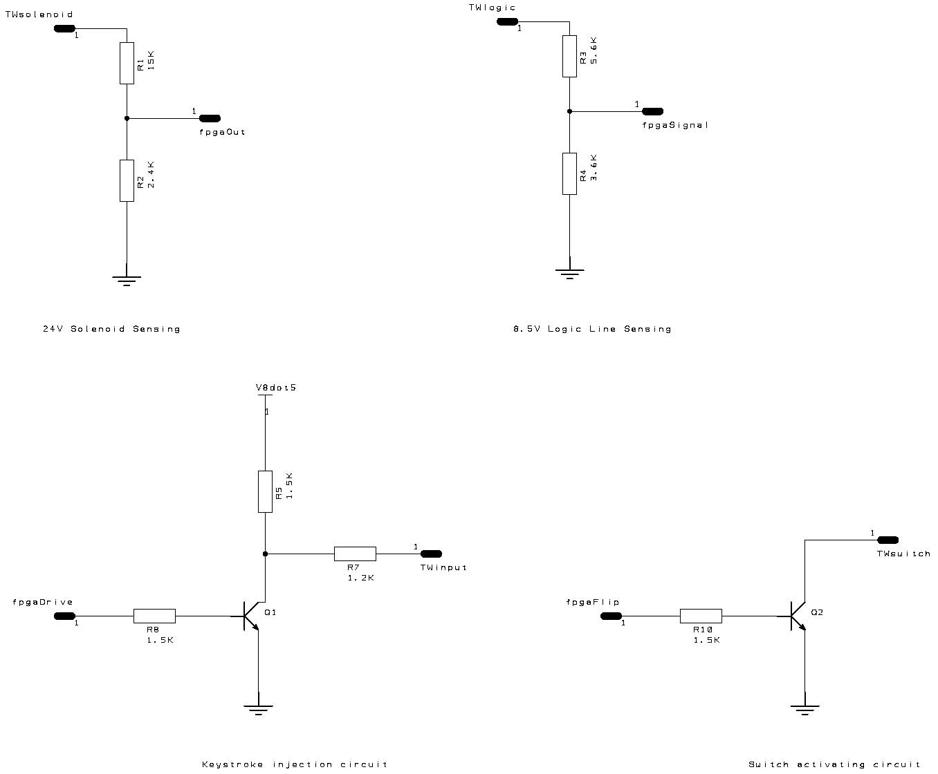 |
| Circuits used on the typewriter interface board |
 |
| Wiring diagram of Memory Typewriter to which I am interfacing |
My next design step is to put my logic analyzer on the typewriter to verify that signals I am monitoring are suitable to use to interpolate the TW Interlock signal expected by the IBM typewriter adapter logic of the 1130. Because of the voltages involved, 8.5 and 24, I have to wait until I can use the adjustment circuits on my interface board, else I will fry the analyzer. All this requires that I wait for the parts that are on order, then complete the board first.
DISPLAY PEDESTAL COMPLETION
The connectors and connections between the LED boards and the LED driver board are very fragile and easily disconnected especially with any twisting of the cables. I replaced a number of the connector inserts to improve the quality of the connections, but mostly it takes enormous patience and hours of work to bend and form everything so the board will remain in place and connected inside the box. My frustration point is reached after 20 or 30 minutes of whack-a-mole, where any minute change results in connectors twisting partially off or connector insets backing out of the housing.
Several intervals of an hour of utter frustration went by, as I adjusted and tweaked and finessed and micro-altered and caressed and patted this into place, but finally I had every thing cabled up ready to close the pedestal box up. The logo plate is bolted atop and I began to screw in the three dozen sheet metal screws around the back.
Alas, as I was a bit more than halfway done, the unit twisted away from me and the front plastic light panel popped off, scraping a huge ugly clear hole through all the layers of paint. I had to walk away and stay away for a while, but I am hoping upon hope that the 3/4" diameter hole is in a section that was away from any LED. If so, I can oh so carefully mask this and spray new black paint to fill the defect. It may still be visible on close examination, but if it is covered then it will live as it is for a while.
If the unit were already bolted onto the frame, the twisting would not have occurred, but the section where this attaches is at the typewriter mount, which has all been thrown into the air by the acquisition of the new and more faithful typewriter footprint. I will ignore this for at least a half a week, until my hatred ebbs and the tedium and frustration heals under a new psychic scab.
POWER SEQUENCER UNIT
I need a power sequencer to bring the various power supplies up in proper sequence. I will use a bank of relays activated by a simple timing chip circuit, adjustable delays until I know for sure what sequence and timing works well. I have multiple power supplies, two for the keyboard, one for the fpga, one for other logic boards in the unit, plus will have the typewriter to turn on, the disk drive inside the frame, and some kind of remote turnon for other peripherals.
This unit will also be responsible for playing the startup, shutdown and normal fan sounds of the 1130 from digital recordings I will make at the National Museum of Computing in Milton Keynes, UK this December. I need a small playback unit for the various sound effects. I have found a suitable bit of hardware, the FTDI Vmusic3 which I can control from the fpga by an SPI link, commanding it to play various mp3 files on a usb memory stick. I have to install a speaker and power amplifier along with that unit which should arrive in a few days.
I can start with a series of switches inside the frame or even manual insertion of power plugs into a power strip, to get the rough sequence worked out, before I begin encoding the sequence in my design.
I was struck by a flash of inspiration - the ET50 could be approached in almost exactly the same method as the new Memory 50 typewriter, hooking to the logic board in place of the physical keyboard, shifting the major burden of driving the mechanisms to the IBM build circuitry. It makes the adapter I have to build much simpler and more straightforward.
There are a few differences between the two typewriter types, for example the ET50 uses 5V for logic signals and 12V to drive solenoids, while the Memory 50 adopted 8.5V for logic and 24V for magnets. Even though the ET50 is a selectric III style (96 character typeballs) and the Memory 50 is a selectric I (88 character type elements), the keyboard interface is very similar.
Where the Memory 50 produces a strobe pulse mechanically to inform the logic board that the tilt and rotate codes have stabilized, the ET50 has a simpler approach where they wait 5ms from the first line that changes until they assume the tilt/rotate codes are stable.
The ET50 adapter now only has to handle:
- code translation from 1130 BCD style tilt/rotate to the ET50 correspondence style tilt/rotate
- convert functional commands like space and tab into ET50 tilt/rotate codes
- convert margin and tab set or clear operations into activation of the 'code' key plus injection of the
appropriate key
- interpolation of the interlock signals similarly to how it is done with the memory 50 typewriter adapter
- managing the hidden shift problem where the 1130 thinks a character is lower case but the ET50 has it
on the upper case side, or vice versa
I spun off an ET50 version of my new electrical interface board I designed for the Memory 50. Ideally, I will soon have two different typing mechanisms that both work properly with the 1130 replica. I intend to debug and refine the adapter logic with the new typewriter, then make the slight modifications for the ET50 and debug that version.
I will still use the Memory 50 as the primary console printer for two reasons - it is the right width to fit in the 1130 footprint and design proportions, and it is a more rugged heavy duty machine.
After hunting for an hour in vain for the logic board I had removed from the ET50, I discovered it had accidentally made its way into a pile of electronic scrap and had been sitting outside in the rain and sun for a few weeks. Fortunately the recyclers hadn't run a free pickup in the area or its whereabouts would have been an unsolved mystery.
I have restored wiring to the cable connectors and put the logic board into place in lieu of my interface board, but it does not appear to be happy or perhaps it was damaged by its sojourn in the trash heap.
The power supply is not delivering the 12V or 5V supplies to the rest of the board, yet the -5V sense line is active. When I put the power supply cable on my board, everything lights up, so the problem is with the hookup and IBM board.
I unhooked all cables except for power, but still have the problem, verifying that it is not a wiring issue elsewhere in the typewriter. I might have a grounding problem, which I will investigate next, although I really don't want to divert too much time to this given it has no direct role in the 1130 replica.
No comments:
Post a Comment