My keyboard arrived today! Excited because it is very close to the IBM keyboard in appearance and operation. I disassembled the unit, adjusted it slightly, and verified that it does what I want:
- has mechanical interposer that forbids more than one key to be depressed at once
- keys latch down and are released by a solenoid, thus the keyboard is 'unlocked' by XIO
- all lamps work, so I should be able to interface the photocells that read the various key codes
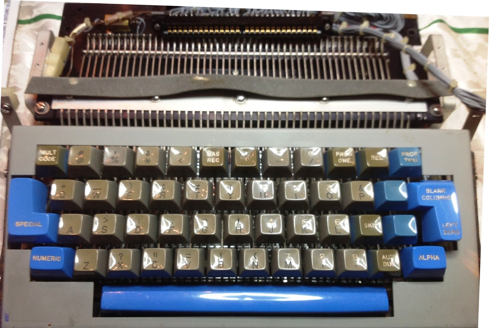
 |
| Keyboard mechanism I will adapt as 1130 keyboard |
I did some rough work to validate the voltage for the lamps and solenoid - lamps seem to work
well at 12V, distributed in series across the ten bulbs that illuminate the 10 photocells. The solenoid works cleanly at 24V, which is reasonable in concert with the 12V lighting circuit (which would be center tapped from a power supply producing +12V and -12V to yield 24 across the solenoid).
 |
| Lamps visible at bottom, interrupted by keys to encode character |
I completed measurements of the resistance of the photocells when illuminated and when blocked by a tab on some key lever. The dark resistance is at least 3 Megohms and the resistance with light falling on the cell is about 10Kilohms, quite a swing and very easy to convert to a digital signal. I will now design the detector circuit, and begin building a prototype for detectors, solenoid operation and microswitch debouncing, all multiplexed to the fpga, from which I can build a production interface board that will be used in the final machine.
 |
| Key levers that latch down and interrupt selected light beams |
Still to do - validate each key cap legend against the 1130 keyboard, work out a plan for modifying those that are different, and adjust the keyboard to maximum fidelity. Certain 1130 keys activate microswitches rather than operate the mechanical levers, so I have to convert this by removing the latching bits and installing a microswitch. The two large end keys are not used on the 1130, for example, so that they will be removed and the key stem hidden under the metal plate into which the keyboard is installed.
 |
| Keyboard as it is now |
 |
| Actual keyboard on an IBM 1130 for reference |
This appears to be almost exactly the same size as a live 1130 keyboard. The key coloring is off a bit and the shapes of the keys is not identical to IBM, but evocative enough for my purposes.Once I remove the unneeded keys, adjust the legends on the keycaps and color one keycap blue for the upper left position, I will have my keyboard.
 |
| Planned changes to keyboard |
The picture above shows the plan for converting the keyboard. The upper right blue keycap is removed and placed on the keystem to its left, with the legend altered to "int req". The upper left gray key has to be recolored to blue and have its legend changed to "rest KB". Several gray keycaps will have their legends removed to become plain. The large keys on the far left and far right are removed. The blue "alpha" shift key on the lower right will have its legend blanked. The blue keys on the right side will have their legend changed to "eof" and "erase field". The gray keycap to the left of the new "erase field" legend will have its legend changed to "<--". The blue key mechanisms will be altered so that they activate microswitches but are not part of the interlocking/locking/photocell mechanism. NOTE - after further research, only the Restore KB and Numeric keys are pure microswitch types, the rest participate in the interlock scheme. I will add microswitches to these two stems and try to disable their blocking of light beams, but will accept the potential error if Numeric or Rest KB is pushed while another key is already latched down. I could probably detect that situation and block it in my interface logic, which will eliminate the concern.
Since my typewriter is a wider platen than the real 1130's, I will have a scale problem with the console printer. By minimizing space from the sides of the cover to the mechanism, I can limit the total effect a bit, but likely I still have a wider printer cover than the actual 1130 features. My current estimate is that it will end up 24" wide whereas the 1130 cover is 20" wide, exactly the same width as the black portion of the display light pedestal and of the black metal which supports the keyboard, lights and buttons. Since the tabletop is about 26" wide in total, the effect will be noticeable. Below is a projection of what it might look like, with the actual 1130 console following it to allow a quick comparison. I will look into coloring the extended sides gray rather than black to minimize the effect of the change, allowing the extended width to blend into the gray flat areas to the sides of the printer cover. That design is illustrated as a third picture below.
 |
| How printer width might distort the replica |
 |
| What a real 1130 looks like, for comparison |
 |
| Concept of coloring to minimize distortion from larger printer cover |
I will probably add an MCP23017 chip onto the I2C link that currently services the two providing my 32 button/switch inputs from the physical console, with the additional link offering me 16 lines to use with the keyboard. After reviewing the codes returned by the photocells, I will not need all ten photocell signals routed to the fpga. Nine are sufficient, as one is used for the Alpha key which is disabled in the 1130 model I am replicating and will have a blank keycap. The KB Rest key will directly drive the restore magnets in the keyboard as well as reporting as a signal to the fpga.
I have already removed the end keycaps that are superfluous and relocated one blue keycap over to its new position as the Int Req key.
 |
| Superfluous keys removed on keyboard mechanism |
I discovered that a number of the keys were originally the blue color, but had been dyed or painted over partially to make them brown. If I can remove the dye I will have the blue key I need for Rest KB position and can potentially dye all the tan and brown keys to the IBM gray color.
 |
| 'Aux Dup' key shows blue original color and recolored top |
I brought a spare keycap to TAP Plastics for advice on the material type, dying, removing dye, and ways to fill in the etched legends on those keycaps that should now be blank. That also will permit me to etch replacement legends for the few that are changing or that are currently blank but should have text on them. They identified the material as injection molded ABS and suggested repainting with enamel paint rather than dying. ABS does not take dyes well. I bought an airbrush and good modeling enamel paints, will practice on the spare removed caps first to get the process and colors right, then fix the necessary keys.
If I had to change any key to stop it from participating in the mechanical locking (latching down until restored), I would only have to snip off the end of the keylever, as you can see in the closeup where the 'Alpha' key is so modified permitting it to be activated even when the remaining keys are latched.
 |
| Lever directly under centered blue key 'Alpha' has tab cut off so it wont latch |
At this point, I don't expect to have to modify any keys to interface this to the 1130 system. After I have completed the key modifications and built the interface board, a modest bit of logic in the fpga will complete this. The fpga will need to start a timer when the first photocell signal is activated, waiting long enough for any other photocell channels to assume their final state before decoding them. It will have to translate from this keyboards encoding to the lines that would be produced by the IBM keyboard.
Certain of the keys are converted into separate signals for the 1130 adapter, among them are Erase Fld, EOF, Int Req, Space, Backspace, Numeric and KB Rest. Essentially, the blue colored keys get this special treatment, although backspace is an exception, colored grey but strobing its own signal rather than a data pattern. The others will activate values on a set of data lines (12, 11, 0, 1 - 9) except for the numeric, which simply toggles a state to determine the mapping of key to the data line values. Since the IBM keyboard is a leveraged part from an 029 keypunch, it emits hollerith code (e.g. A is 12 + 1 signals, S is 0 + 2 signal, digit 4 is 4 signal). The keyboard I am converting produces a modified version of hollerith, but the translation is straightforward for most keys.


No comments:
Post a Comment