I worked on rewiring the LED matrix boards that will light the inside of the display pedestal. It took a while to finish the rewiring because I was using a brush on conformal coating that is an insulator, in lieu of vinyl electrical tape, which is important given the criss-cross of wiring and the linking of sections to pack the digits.
 |
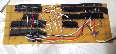
| Finished left side of display panel LED matrix (seen from rear) |
I had carefully checked the spacing of the right hand half, and double checked the assignments of lights to the third MAX7219 digit and segment positions, to ensure there are enough control lines left to operate the lights on the main desk on the left and right of the keyboard, since this right board has a number of 'sparse' rows and a naive implementation would require almost two 7219 chips, but with the right packing of the bits together it fits into a single 7219 using only 7 of the 8 digits.
 |
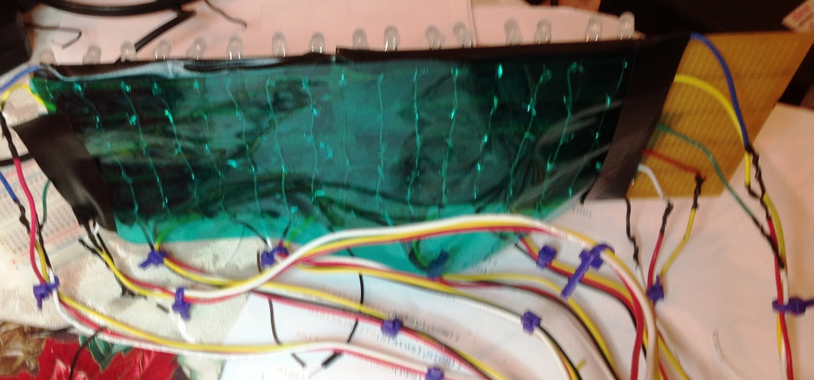
| Left side of LED matrix, front view. A grid in front will separate the lights into cells behind a 'smoked glass' plastic faceplate . These lights are the contents of six of the 1130 registers. |
I found a couple of errors in the complex right hand board which I will correct tomorrow, then do a full scale test of the driver board and light matrix. As a quick and dirty way to make use of the light panel before I build the actual enclosure that will host it as a pedestal, I will put the LED boards and the rotary switch on a triangular mailing tube that is roughly the size of the enclosure face.
 |
| Starting the wiring of the right hand panel with its 'packing' of lights in different sections. |
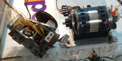
I worked on the paper tape reader next, checking the operation of the photocells, timing strobe, stop/start solenoid and motor control functions. The reader has a sensor array rather than individual photocells, so I need to make sure I understand all the requirements before finalizing a design. I will also need to determine the right voltage to operate the solenoid that releases the clutch to move the tape forward for reading. I replaced the incandescent (flashlight) bulbs in the reader with leds for reliability.
 |
| Reader mechanism with LED lights replacing incandescent lamps. |
The interface logic is going to be similar to the keyboard interface, in that it is mulitplexing photocell channels but there are some control signals to start and stop the motor, for example, that flow out from the 1130 over the same channel. Since I have all those extra MCP23017 chips due to the ordering malfunction by Arrow's web site, I can build a number of similar interface boards for the various peripherals to be attached.
I will do a quick breadboard tomorrow to establish the resistor values for reliable detection and to get the relay driver for the motor working properly. The motor runs on 120V utility AC, which I will switch with a relay controlled by the interface, and route 3.3V for the LED lamps in the tape reader.. Even when I make a design for the interface board, I will not order it yet, since it makes sense to add on the logic required for the Tally paper tape punch which I have not yet designed.
 |
| Beginning to investigate solenoid, motor control and photodetector array. |
I worked on the design of the strobe interface, which I will also put up on a breadboard and test tomorrow.


No comments:
Post a Comment